
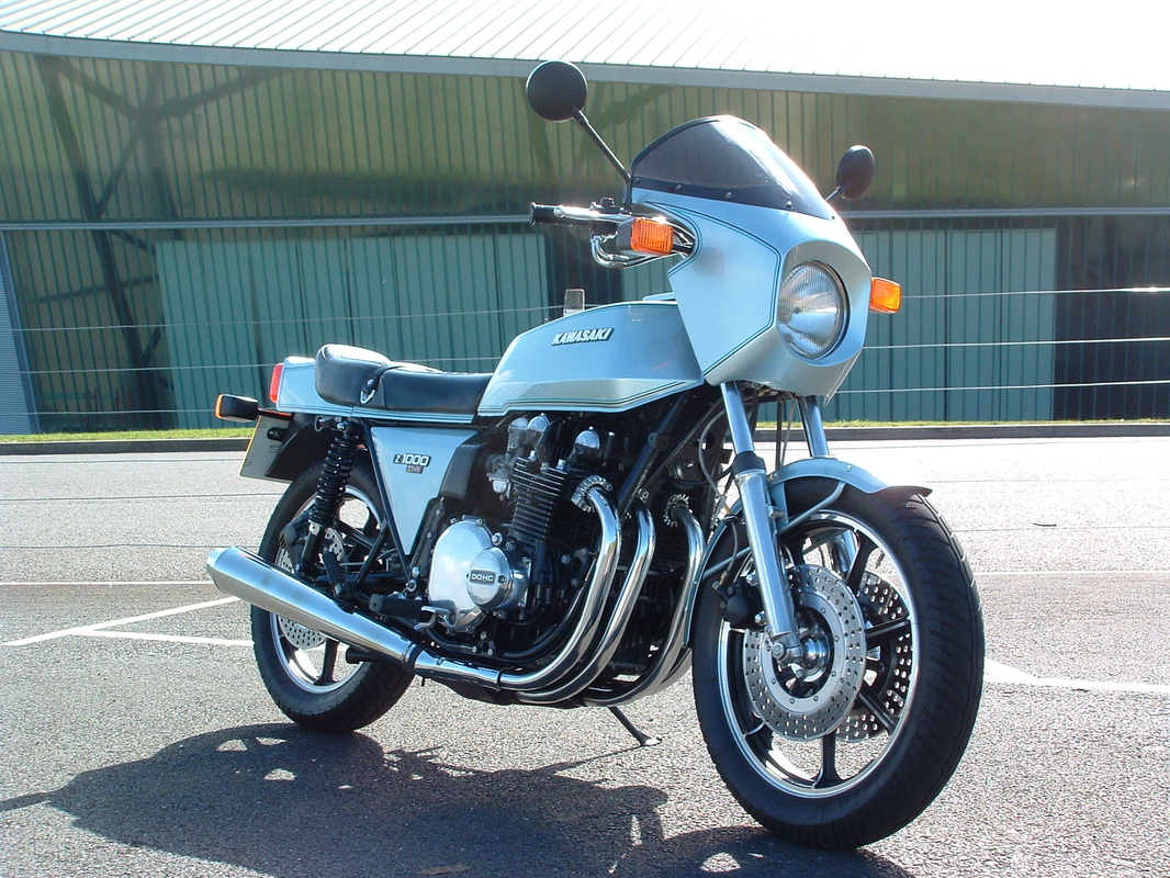
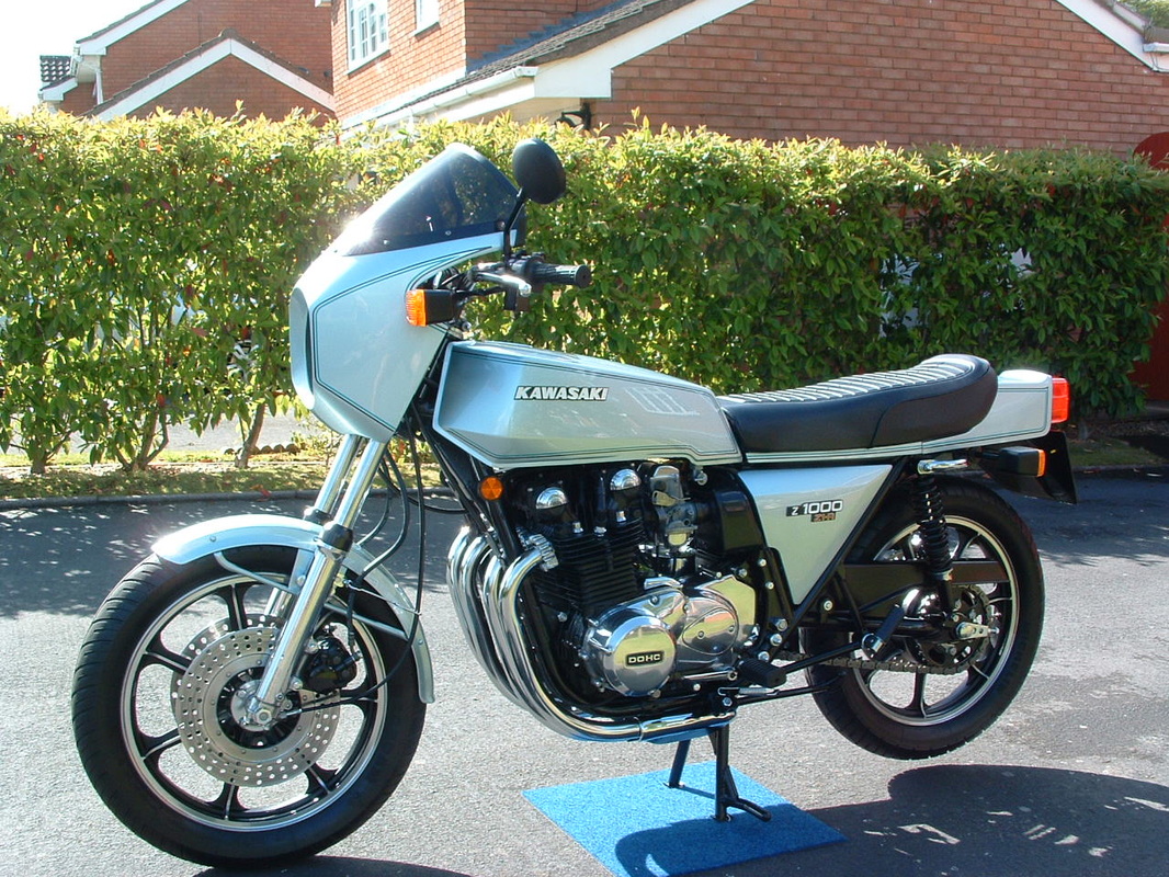
Z1-R 1978's King Kawasaki
This 1978 machine lived in Italy until 1995 when it was brought to the UK.
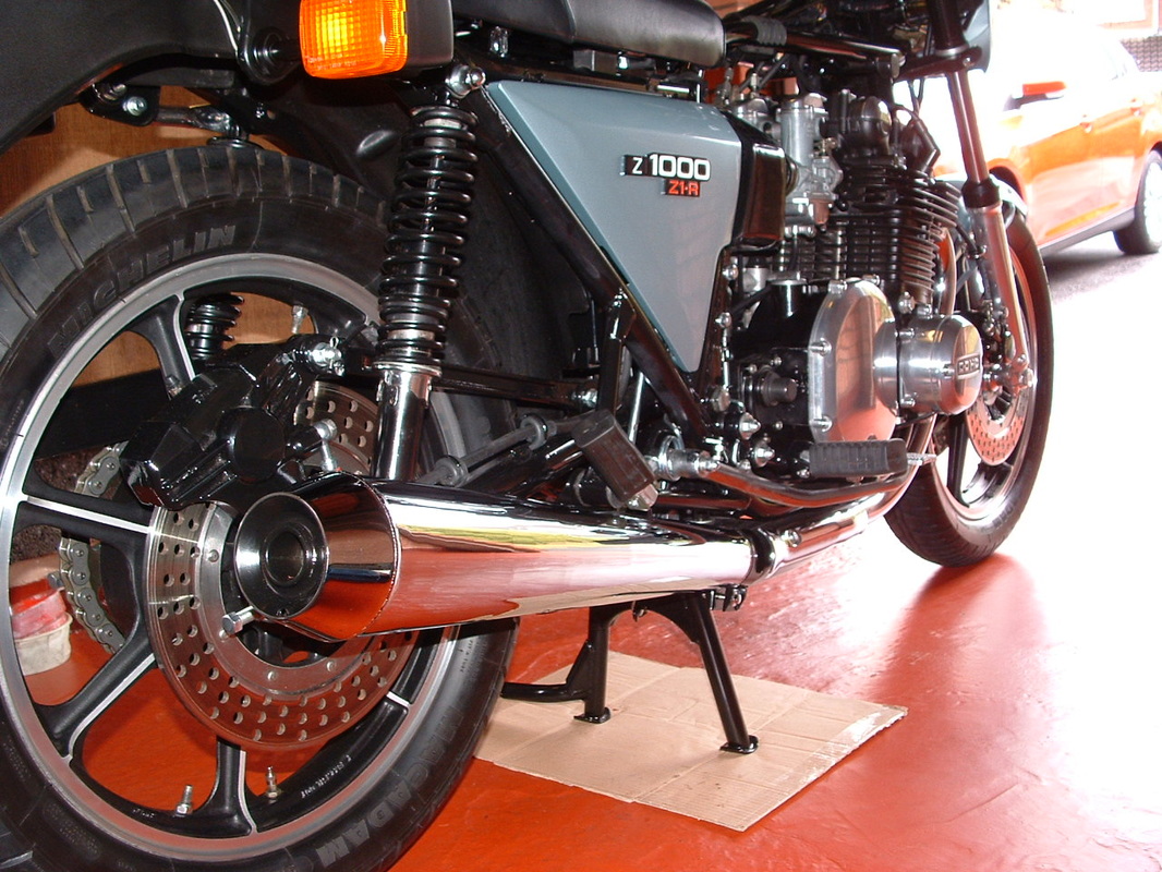
The Z1-R was top of the Kawasaki range for 1978, including many upgrades that were being sold as after market parts for the Z1000 models.
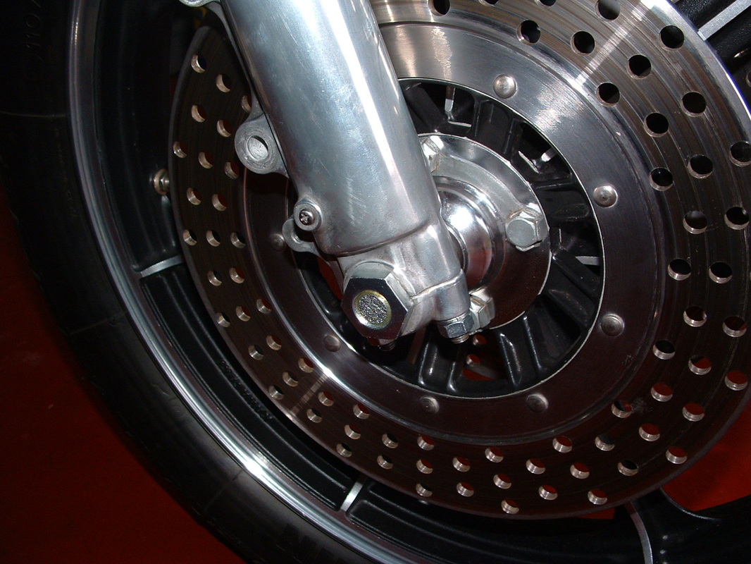
It contained many firsts for Kawasaki - such as multiple drilled brake rotors.
The Z1-R is now recognised as the first Japanese Café Racer - and it has become very sought after around the world.
The Z1-R was top of the Kawasaki range for 1978, including many upgrades that were being sold as after market parts for the Z1000 models.
It contained many firsts for Kawasaki - such as multiple drilled brake rotors.
The Z1-R is now recognised as the first Japanese Café Racer - and it has become very sought after around the world.
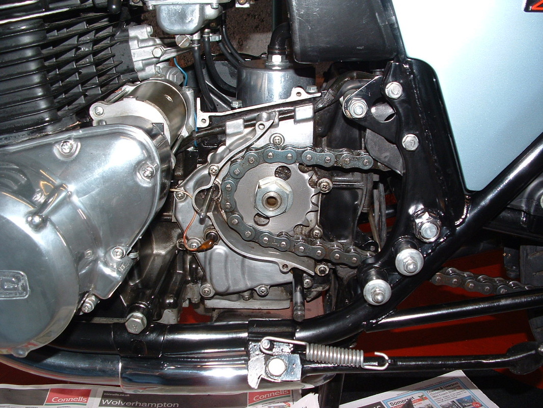
Transmission Detail
Original chain & sprockets in unworn condition is a good sign of low mileage.
The inner transmission cover is all intact and the correct nuts, bolts and fasteners seem to be all there.
Happy Days !!
The inner transmission cover is all intact and the correct nuts, bolts and fasteners seem to be all there.
Happy Days !!
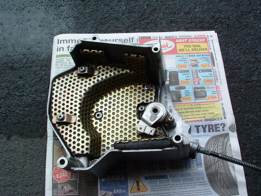
Sound Dampening Foam & Baffle
These bikes had thicker crankcases and extra sound damping inside the engine cover - to reduce engine and transmission noise.
Years of chain lube have kept the internals in good condition.
Years of chain lube have kept the internals in good condition.
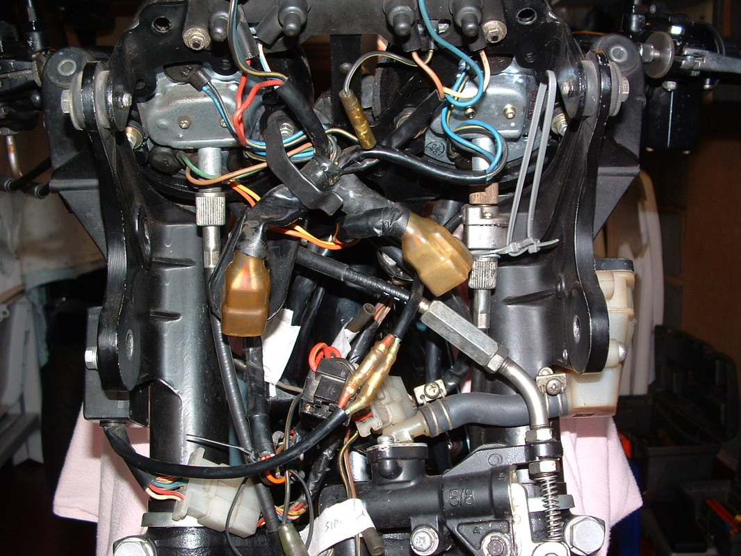
Electrical Items behind fairing
There is much more electrical equipment behind that sleek new fairing - compared to the original Z1 models from 1972 onwards.
The Z1-R featured self cancelling turn signals, a fuel level gauge and an ammeter in the cockpit display. More firsts for Kawasaki at the time.
The Z1-R featured self cancelling turn signals, a fuel level gauge and an ammeter in the cockpit display. More firsts for Kawasaki at the time.
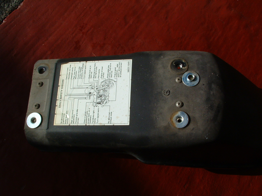
Rear fender with damper plate attached
More signs of the extra build quality and sound deadening here - The rear fender is moulded from abs and has a metal damper plate built into the underside.
You can just see the four small retaining screws in this shot.
You can just see the four small retaining screws in this shot.
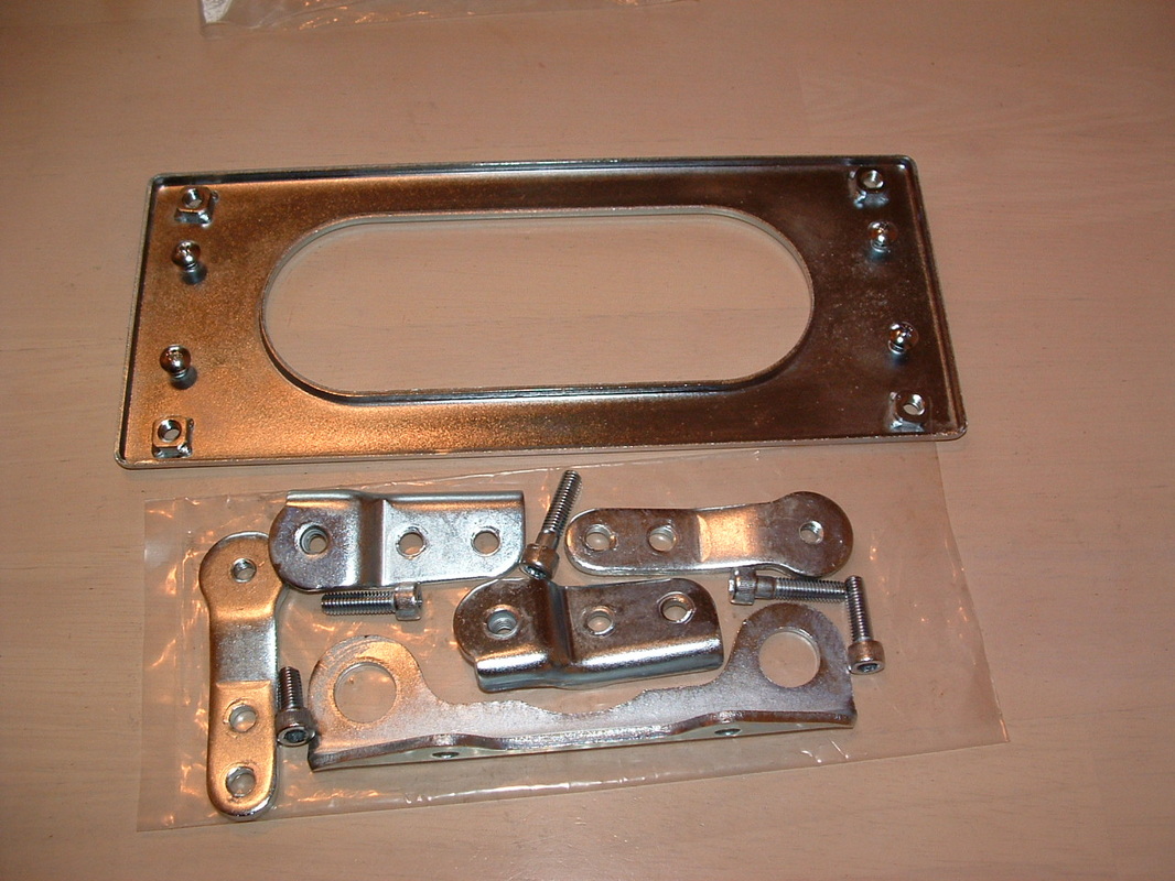
Fender damper & fairing brackets
Here is the damper plate from the rear fender - removed and re-zinc plated ready for re-assembly. We left the tiny screws on the plate during the zinc process, so they would not get lost !!
The other brackets in this shot support the fairing where it joins the frame.
The other brackets in this shot support the fairing where it joins the frame.
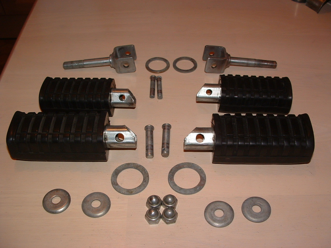
Footrests & fittings
The rear footrest hangers have a long threaded shaft. The right hand one holds the bracket for the 4 into 1 silencer in place.
They are inserted through the frame in the place that early Z1 frames use for mounting twin mufflers on each side.
The correct finish for the brackets is an olive drab effect.
They are inserted through the frame in the place that early Z1 frames use for mounting twin mufflers on each side.
The correct finish for the brackets is an olive drab effect.
Footrests re-finished
Here are the footrests and newly finished rear brackets ready for re-assembly.
remember to fit a large flat washer between each rubber and it's bracket.
The front footrest brackets will be re-painted in the correct black finish later.
remember to fit a large flat washer between each rubber and it's bracket.
The front footrest brackets will be re-painted in the correct black finish later.
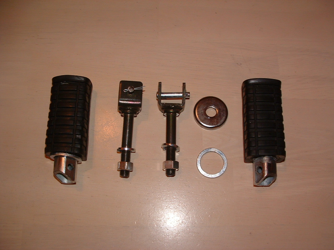
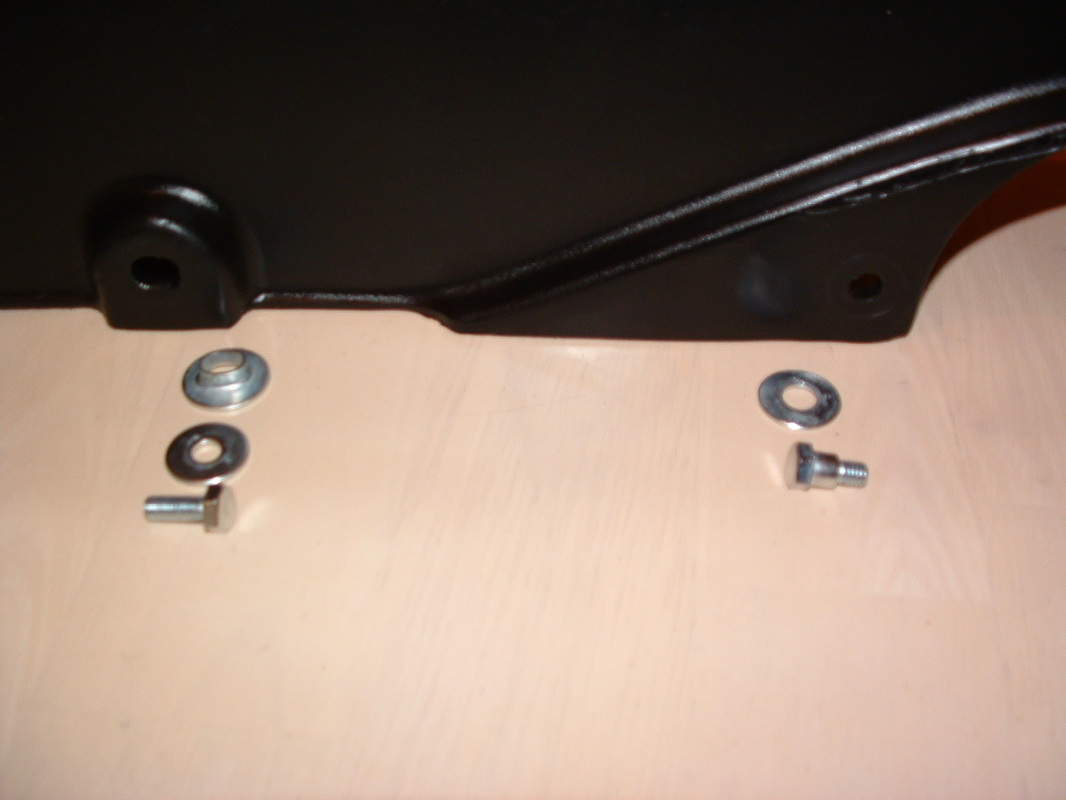
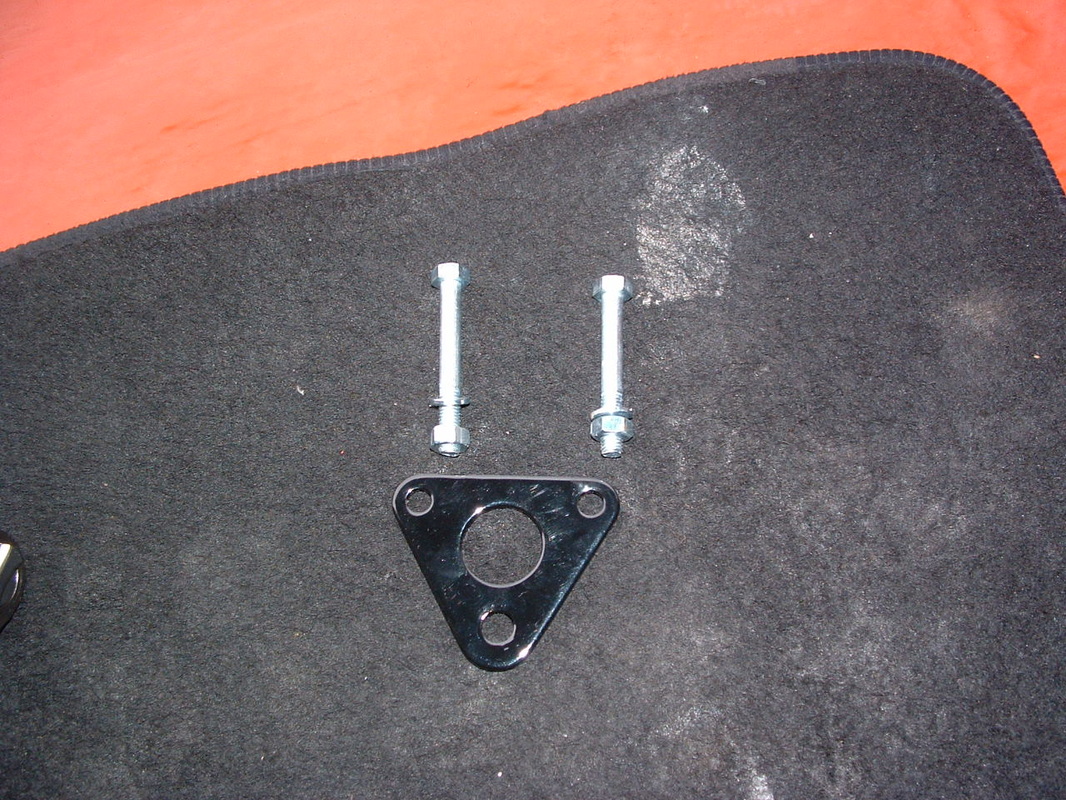
Rear Footrest comp[onents
Time to re-assemble the rear footrests. The correct m10 x 13mm nuts are used to fix them to the frame. There is a large chrome plated dome washer that covers the damper rubber where the bracket meets the frame.
It is shown here but is not in the parts diagram for the bike.
It is shown here but is not in the parts diagram for the bike.
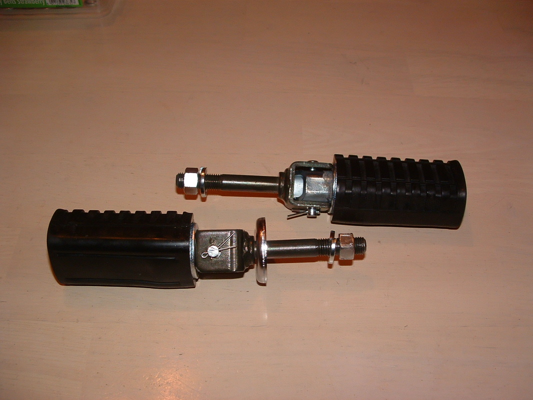
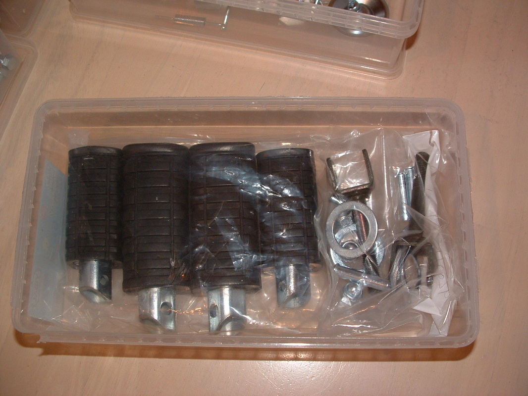
Rear Footrests Complete
The rear footrests are now ready to go back onto the machine.
They can be stored away like this until the time is right.
We will finish off the split pins when we have checked how they look on the bike.
They can be stored away like this until the time is right.
We will finish off the split pins when we have checked how they look on the bike.
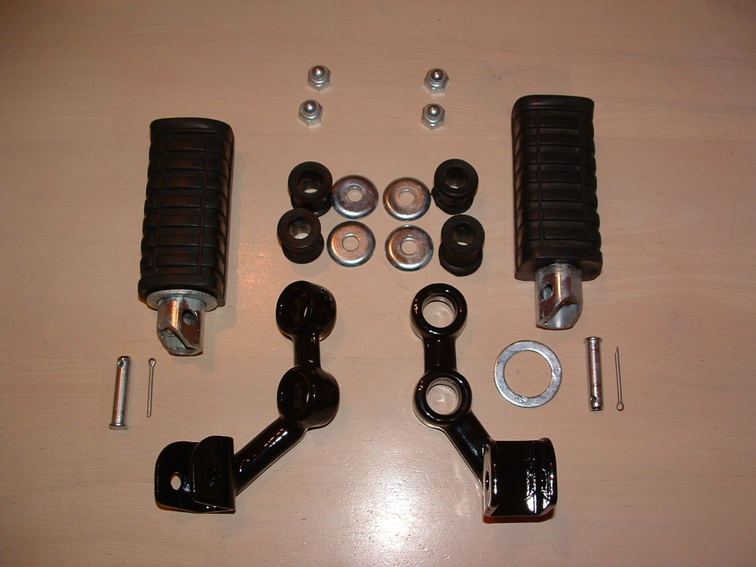
Front Footrest components
The front footrests have these damper rubbers inserted into the bracket - BEFORE the brackets are assembled onto the machine.
Once fitted they will be covered by these four domed washers and 13mm nuts and will not be seen.
Check the rests and brackets on the bike to make sure you assemble them right. The split pin fastener should be underneath the bracket out of sight.
Once fitted they will be covered by these four domed washers and 13mm nuts and will not be seen.
Check the rests and brackets on the bike to make sure you assemble them right. The split pin fastener should be underneath the bracket out of sight.

Front Footrests Complete
The front footrests are now ready to go back onto the machine.
The right footrest has to be tucked up if the emergency kick start lever is attached to start the bike.
The studs they fit onto have a narrow 14mm nut on the inside of the frame to retain them.
The right footrest has to be tucked up if the emergency kick start lever is attached to start the bike.
The studs they fit onto have a narrow 14mm nut on the inside of the frame to retain them.
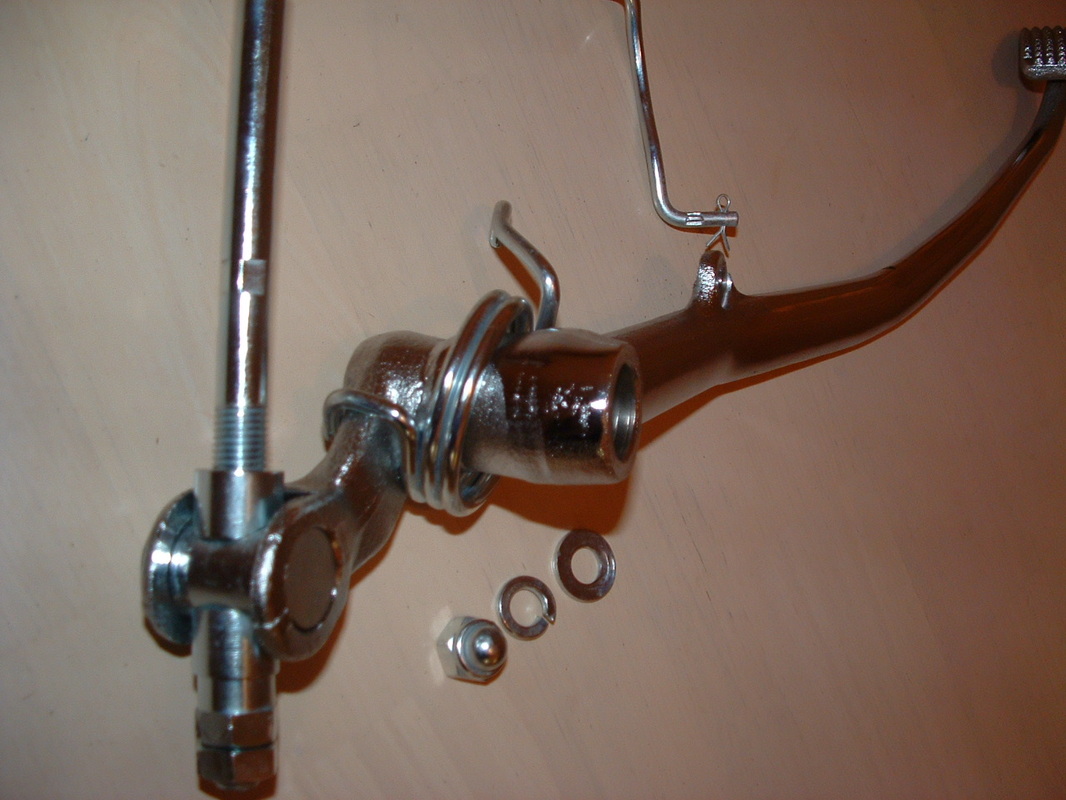
Rear brake adjuster
The rear master cylinder brake action is adjustable via this arrangement on the 1978 model. I think the D3 version from 1980 used a slightly different rear master cylinder.
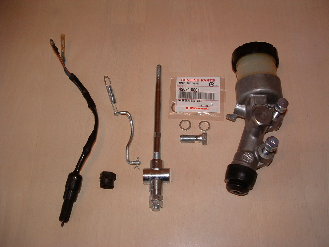
Brake parts ready for zinc plating
Here are a few brake parts - cleaned up and ready for zinc plating.
The threaded adjuster on the brake arm had to be soaked in penetrating oil to free it off after all those years.
The small spring and split pin are left attached to the brake switch link - so they don't get left behind in the zinc plating barrel.
The threaded adjuster on the brake arm had to be soaked in penetrating oil to free it off after all those years.
The small spring and split pin are left attached to the brake switch link - so they don't get left behind in the zinc plating barrel.
Finished brake parts
Here are some of the brake components - back in their factory zinced finish and ready for re-assembly.
The banjo bolts for brake unions have been superseded at Kawasaki - to a black item with a countersunk head. It will do the job, but looks nothing like the originals shown here. They have a zinc finish and a 14mm plain bolt head.
The banjo bolts for brake unions have been superseded at Kawasaki - to a black item with a countersunk head. It will do the job, but looks nothing like the originals shown here. They have a zinc finish and a 14mm plain bolt head.
Rear Brake Lever
The rear brake lever has cleaned up well.
It will not need to be chrome plated again.
Great news !!
This needs to be re-fitted before the swinging arm - to give good access to stretch the awkward return spring.
It will not need to be chrome plated again.
Great news !!
This needs to be re-fitted before the swinging arm - to give good access to stretch the awkward return spring.
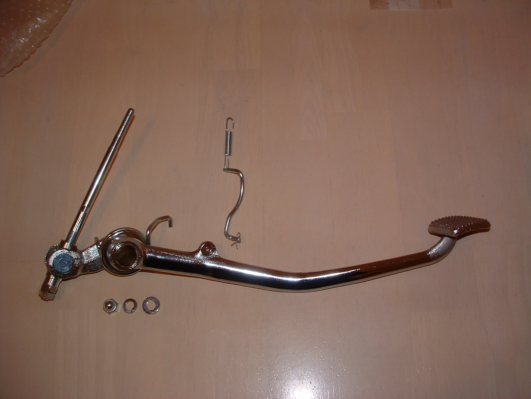
Brake Lever Components
The components go together like this when they are back on the bike.
The domed nut secures the lever onto the frame.
Grease the shaft before fitting the lever.
The domed nut secures the lever onto the frame.
Grease the shaft before fitting the lever.
Return Spring Position
The return spring hooks over the lever like this when fitted.
You need to get maximum upward rotation of the brake lever to slacken the spring as it goes over the frame.
Beware of damaging the paint as it goes on. You can use tape or card to stop scratches - and pull it out afterwards.
You need to get maximum upward rotation of the brake lever to slacken the spring as it goes over the frame.
Beware of damaging the paint as it goes on. You can use tape or card to stop scratches - and pull it out afterwards.
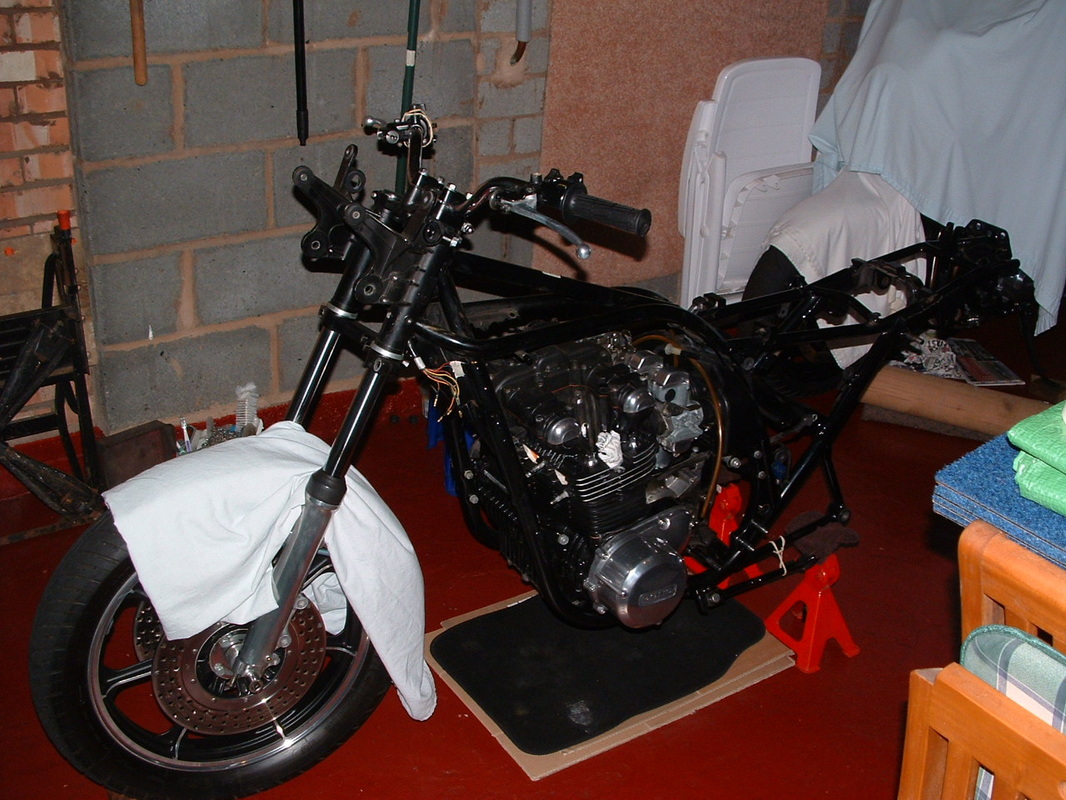
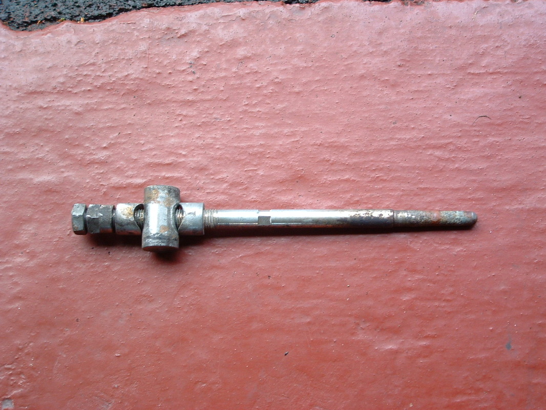
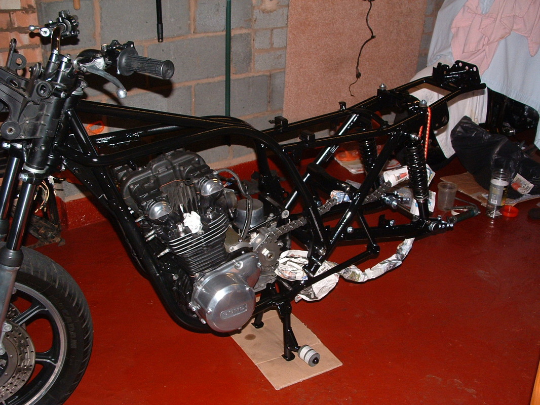
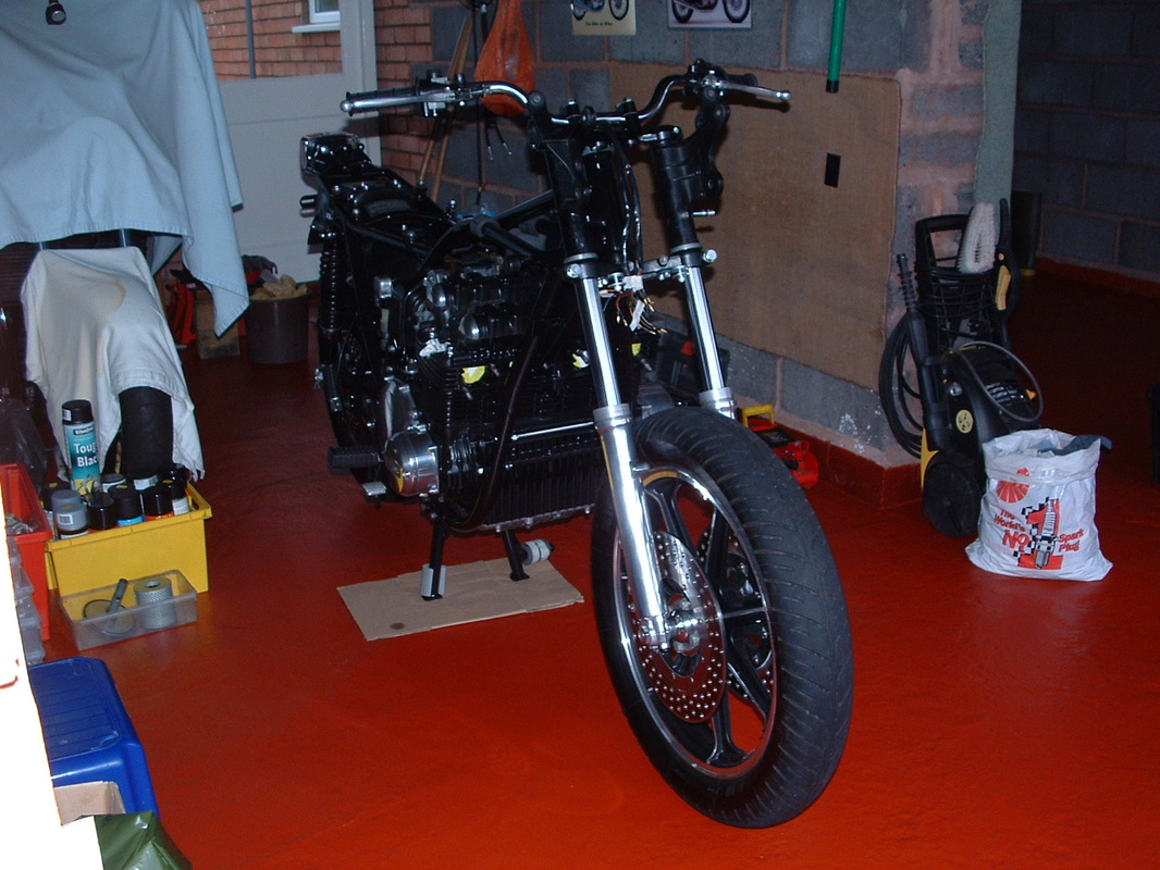
Missing electrics & a wheel
Here is the bike during restoration. The swinging arm is out for re-painting and the rear footrest holders on the frame are taking the strain for now.
The front axle is out for refurbishment and a socket lever is taking it's place.
All the electrics are off the bike for a clean, check and any refinishing that is needed
The front axle is out for refurbishment and a socket lever is taking it's place.
All the electrics are off the bike for a clean, check and any refinishing that is needed
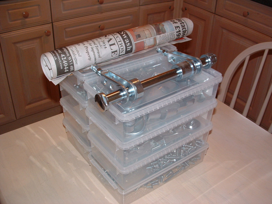
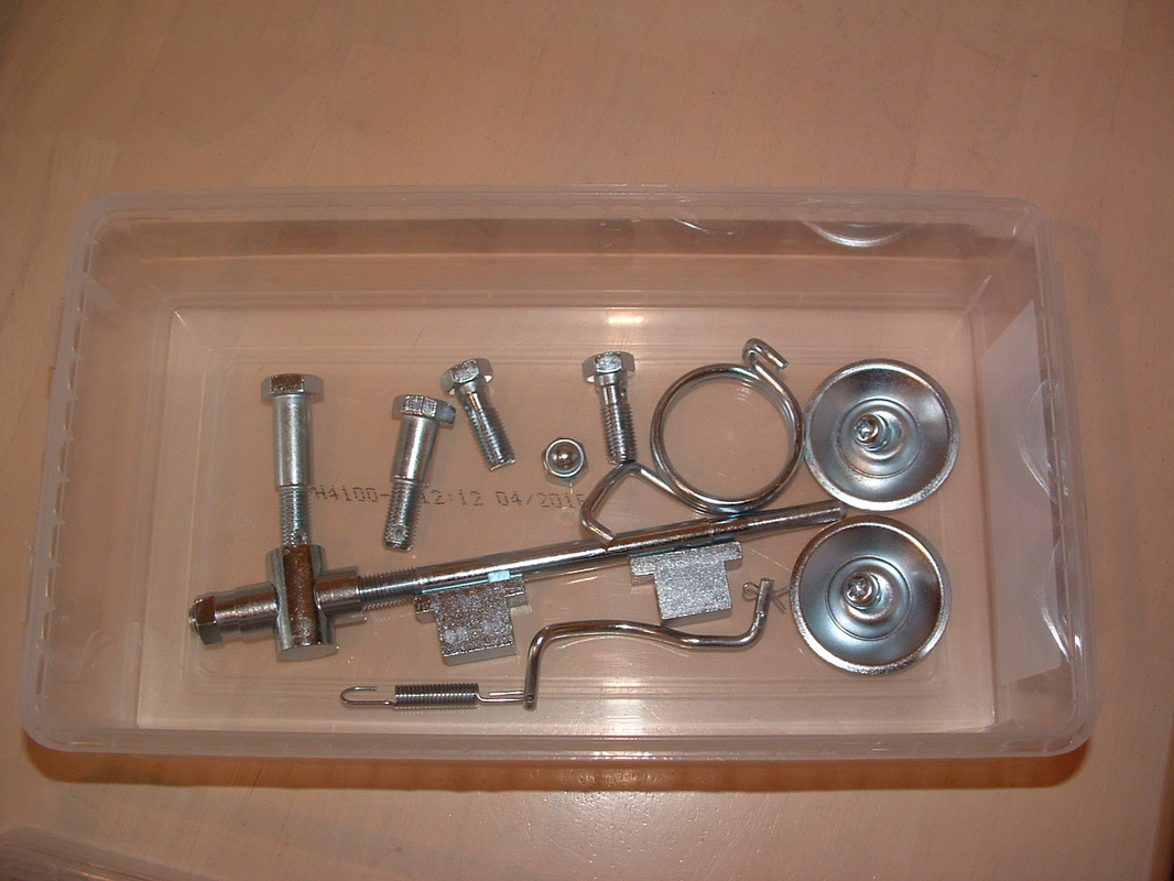
Candy box selection
The rear axle is now ready for re-assembly onto the swinging arm - when it's new paint has gone nice and hard.
Our local candy shop donated plastic containers for all the fresh zinc plated fasteners to be sorted into.
Our local candy shop donated plastic containers for all the fresh zinc plated fasteners to be sorted into.

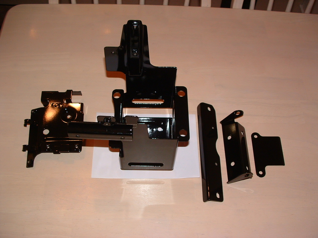
Painted parts de-rusted
Here are some of the black painted parts before re-painting.
Front middle is the kick start lever cover. On this model the lever is stowed under the seat for emergency use only.
We are using a new stop lamp bracket without rear indicator stems.
The battery box and electrics panel will need damper rubbers and metal collars to be fitted before they can accept their components.

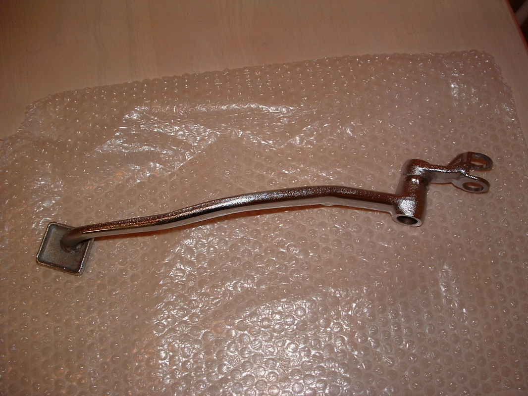
Stands & torque arm
Here are some of the larger painted items ready to go back onto the machine. You can see the rear brake torque arm, front footrest hangers and a bracket from behind the headlamp which holds block connectors in place.
The small satin black holders keep the heat shields in place on the power chamber (collector box).
Can you tell the ones we painted from the professional ones ?
The small satin black holders keep the heat shields in place on the power chamber (collector box).
Can you tell the ones we painted from the professional ones ?

Side Stand Bolt
The side stand bolt had no retaining nut fitted.
It just span round instead of unscrewing.
We had to cut it off and grind out the shaft until it could be removed.
The threaded hole at the rear of the stand was tapped to clean up the threads.
New bolts and nuts are still available.
It just span round instead of unscrewing.
We had to cut it off and grind out the shaft until it could be removed.
The threaded hole at the rear of the stand was tapped to clean up the threads.
New bolts and nuts are still available.

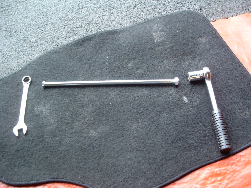
Spring Puller
The main stand is back on now.
Fit it before the swinging arm to give clearance for the spring puller.
The foam will stop the stand hitting the frame until the silencer bracket stop is back on. The foot lever is shorter for Z1-R than the Z1 - due to there being no muffler on that side.
You can see our puller tool - made from a steel coat hanger.
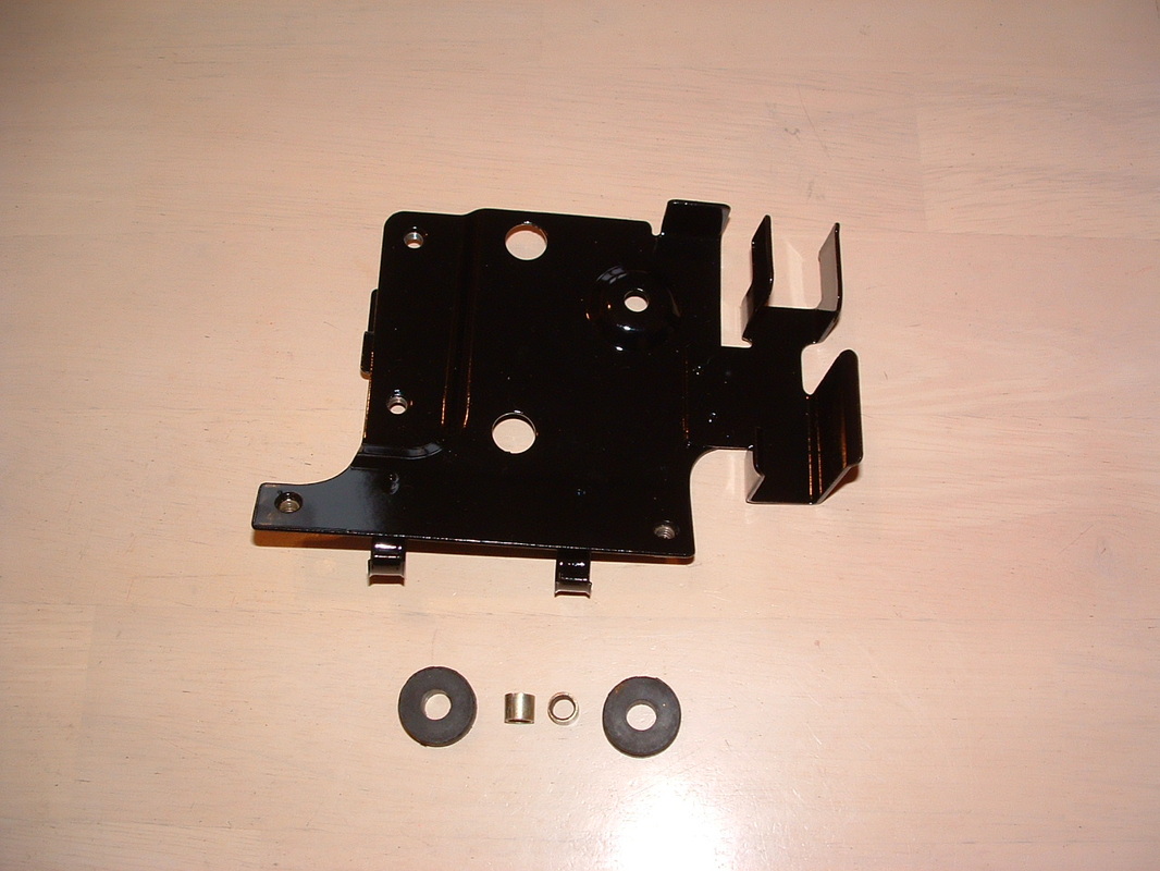
Battery box & electric panel
Here is the battery box and electrics panel ready for re-fitting.
The three brackets to the right are a battery retainer and the two airbox supports - which join together in front of the battery.
We can't wait to get some of the electrical items and the wiring loom back where they belong now.
The three brackets to the right are a battery retainer and the two airbox supports - which join together in front of the battery.
We can't wait to get some of the electrical items and the wiring loom back where they belong now.

Battery box dampers
The battery box needs ten rubber dampers to support the battery.
The four dampers to the right have a collar inside and insulate the battery box from the frame to reduce vibration damage to the electrical system.
The four dampers to the right have a collar inside and insulate the battery box from the frame to reduce vibration damage to the electrical system.

Battery box assembled
Here are the rubbers in place. We have assembled the rear engine brackets to show you how they support the front of the battery box when on the bike.
The air box support is visible at the front of this shot.
The air box support is visible at the front of this shot.
Electric Panel dampers
Fit these two dampers to the centre holes in the electric panel.
It is quite a tight fit to get them in - make sure you can spin them freely when you are done. Fit the two metal collars AFTER the dampers are back on the panel.
Now you are ready to re-fit the components.
It is quite a tight fit to get them in - make sure you can spin them freely when you are done. Fit the two metal collars AFTER the dampers are back on the panel.
Now you are ready to re-fit the components.
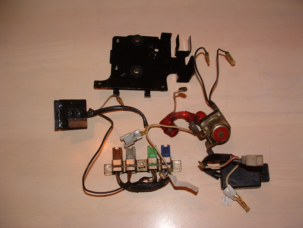
Electric Panel components
You have to fit all these components onto the panel.
Some before photos help to show us how they went together.
Now is the time to check and clean them all.
Some before photos help to show us how they went together.
Now is the time to check and clean them all.
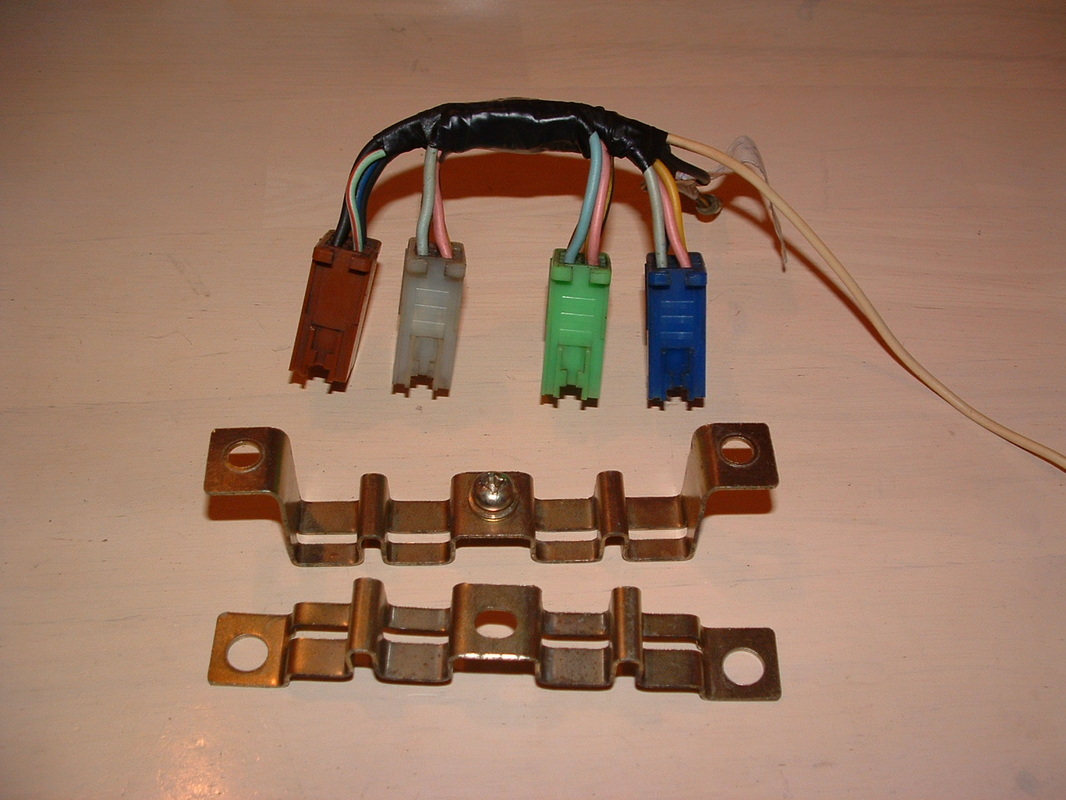
Connector Block cleaned up
The connector block is separated and cleaned.
The original finish on many of the parts is still amazing !!
Check inside the connectors for corrosion and signs of overheating.
The original finish on many of the parts is still amazing !!
Check inside the connectors for corrosion and signs of overheating.
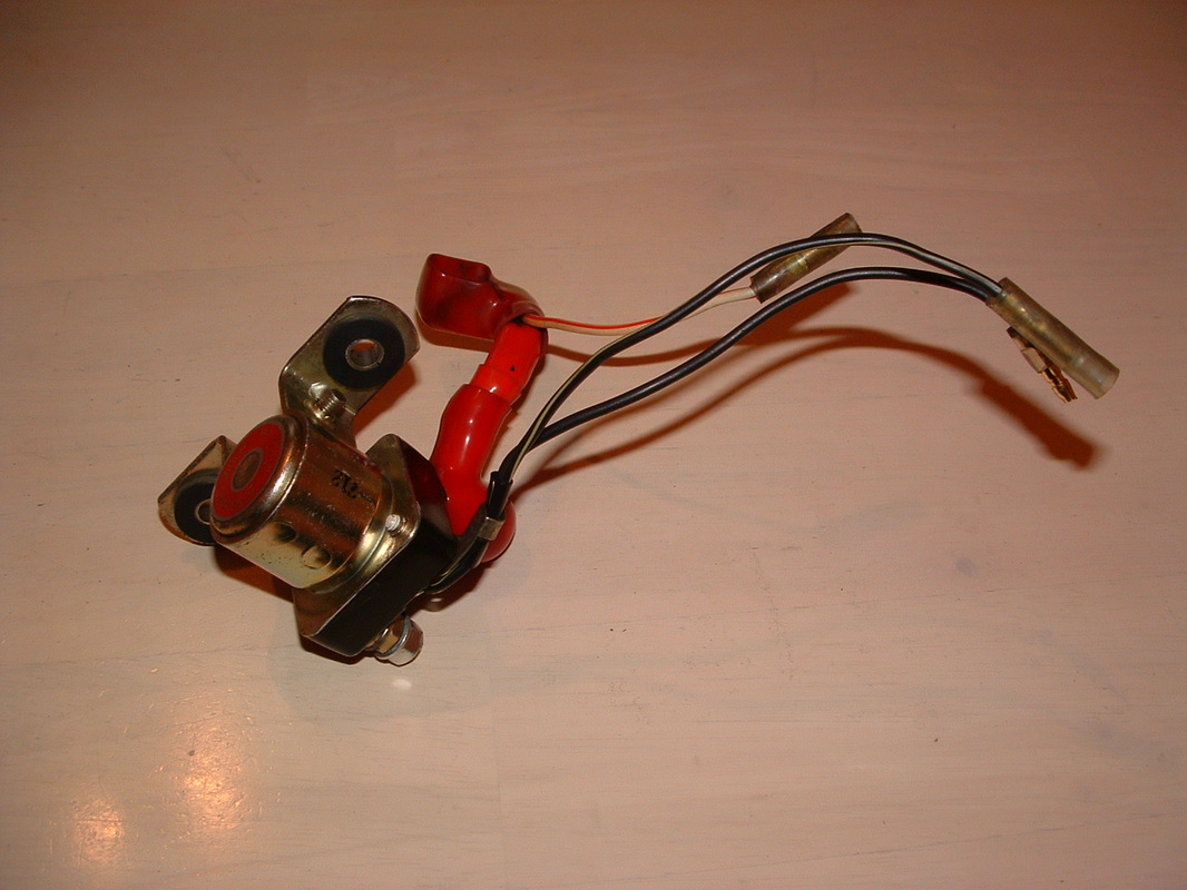
Great original Solenoid
The solenoid has two dampers with collars where it bolts onto the panel.
You can see how well the factory finish has been preserved over the decades.
Even the factory sticker is in great condition.
You can see how well the factory finish has been preserved over the decades.
Even the factory sticker is in great condition.
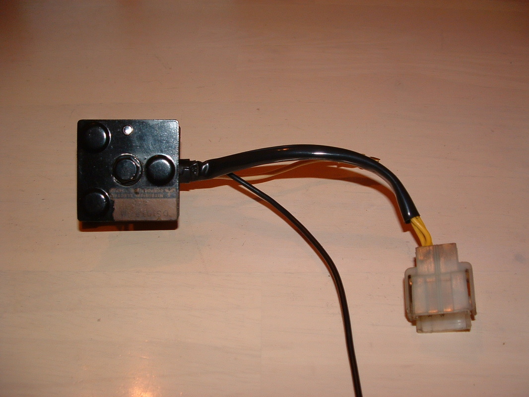
Original Rectifier & markings
The rectifier has also cleaned up well and needs no re-painting.
1978 factory markings are still present and in good order.
Block connectors are colour coded to prevent foul ups.
1978 factory markings are still present and in good order.
Block connectors are colour coded to prevent foul ups.
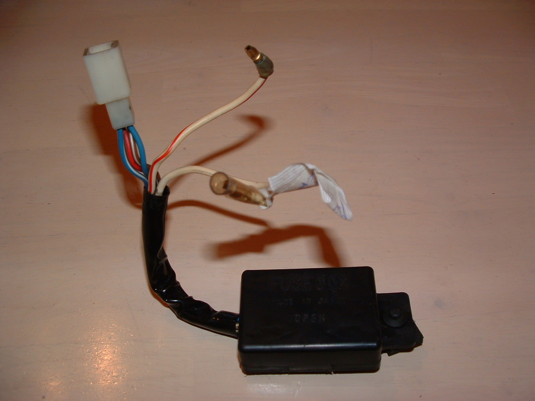
Main Fuse Box cleaned
The main fuse box has a rubber damper at the back.
This slots onto the electric panel bracket.
The box is then on it's side when you look at it.
Spare fuses are carried inside the lid.
** You can get the correct spare fuses from our Cool Parts page above**
This slots onto the electric panel bracket.
The box is then on it's side when you look at it.
Spare fuses are carried inside the lid.
** You can get the correct spare fuses from our Cool Parts page above**

Rebuilt Electric Panel
The components are all fitted back onto the electric panel now.
There will be one extra relay mounted top right when the wiring harness is back in place.
There are two metal hooks at lower rear of the panel.
They support the harness as it passes and stop pressure on the connections causing problems.
There will be one extra relay mounted top right when the wiring harness is back in place.
There are two metal hooks at lower rear of the panel.
They support the harness as it passes and stop pressure on the connections causing problems.
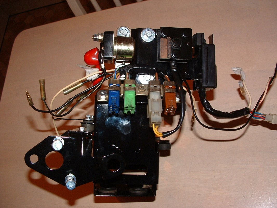
Complete Electric Panel & Battery Box assembly
The electric panel has now been mounted onto the side of the Battery box.
We will clean up and add on the regulator later.
All the components can be stored like this until we re-fit them.
This makes sure we have found out all the correct fittings and we know how they go together. When the frame is in the way it is not so easy to tell !!
We will clean up and add on the regulator later.
All the components can be stored like this until we re-fit them.
This makes sure we have found out all the correct fittings and we know how they go together. When the frame is in the way it is not so easy to tell !!
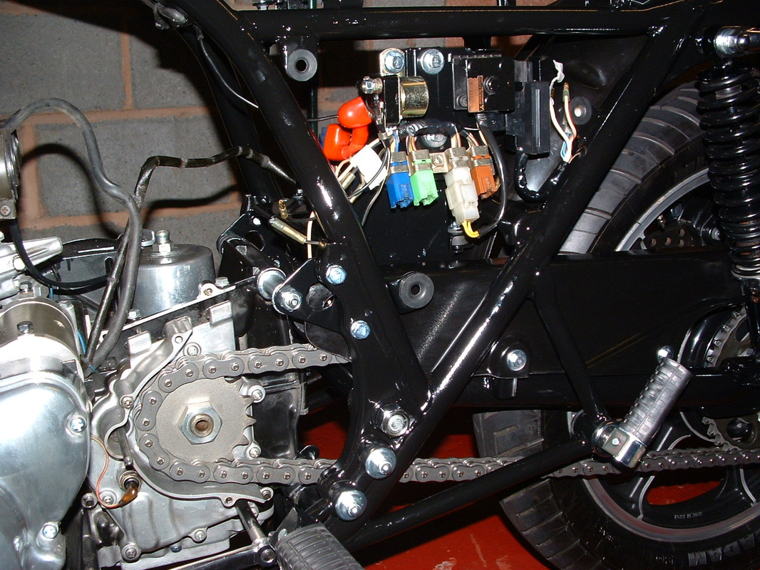
Battery Box & Electric Panel Re-Fitted
This is how the unit will look on the machine.
You can see the airbox support protruding at the front.
A relay will need to hook over the top right of the electric panel when the wiring harness is back on.
.
You can see the airbox support protruding at the front.
A relay will need to hook over the top right of the electric panel when the wiring harness is back on.
.

Re-finished seat pan
Here is the re-finished seat pan.
It needs warning decals, a new foam, strap and a seat cover from Japan.
Luckily the base was solid with all spikes intact.
The kick start lever cover, seat lock bracket and two front seat to frame locating brackets will all need to be bolted back into place.
It needs warning decals, a new foam, strap and a seat cover from Japan.
Luckily the base was solid with all spikes intact.
The kick start lever cover, seat lock bracket and two front seat to frame locating brackets will all need to be bolted back into place.
Front Axle Clamps
The front axle is back in place.
The retainers have an arrow underneath which must face forward.
Tighten the two front clamps until there is no gap.
When you tighten the rear ones there will be a slight gap - that is correct.
Apply correct torque before riding !!
The retainers have an arrow underneath which must face forward.
Tighten the two front clamps until there is no gap.
When you tighten the rear ones there will be a slight gap - that is correct.
Apply correct torque before riding !!
Oil Pan Inspection
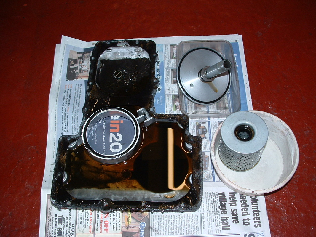
The oil pan needs to be removed for cleaning out and inspection.
Nearly four decades worth of oil sludge will have built up.
The baffle gate stops oil being thrown back under acceleration, but traps sediments in the rear of the sump.
Flushing & changing your oil will not work here - as you can see.
Also inspect the strainer gauze under the oil pump - it can get blocked and this is your only chance to see it !!
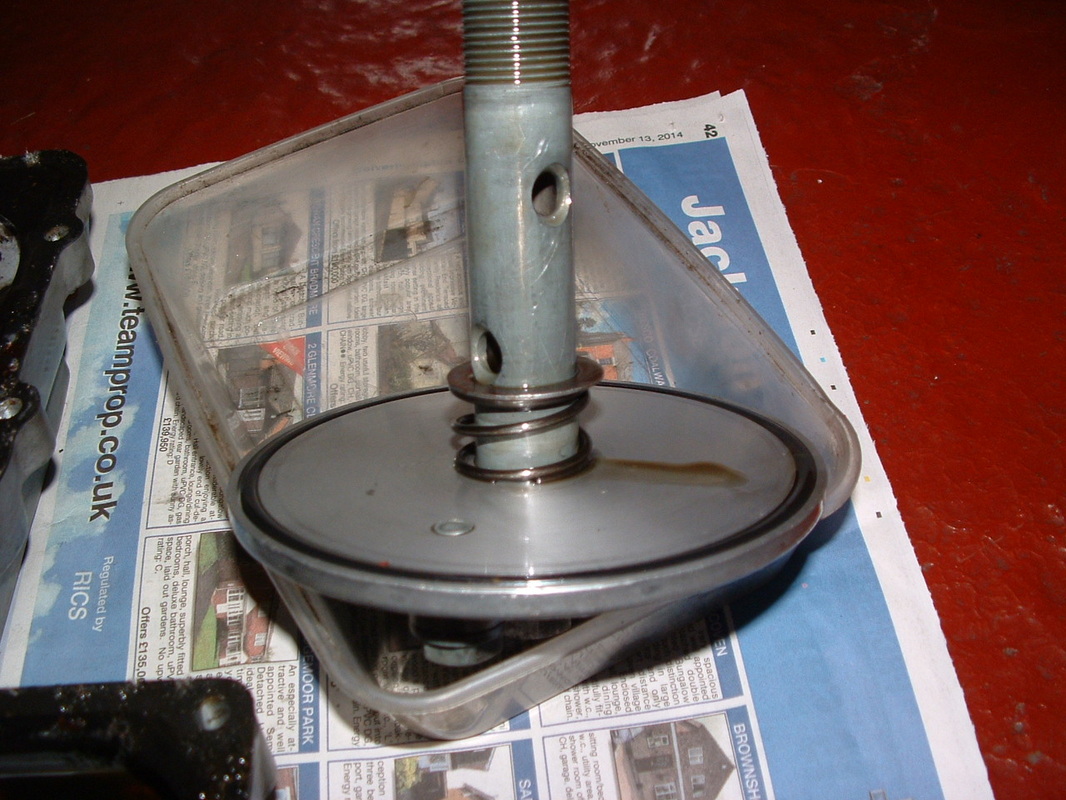
Oil Filter Spring & Washer
Four O rings need changing during this operation.
Make sure you have the spring and washer fitted on the filter bolt in this order.
That will locate the filter correctly against the crank case.
The washer can easily get stuck to the base of your old filter and be thrown out by mistake !!
Change the large O ring here and the small one on the head of the filter bolt.
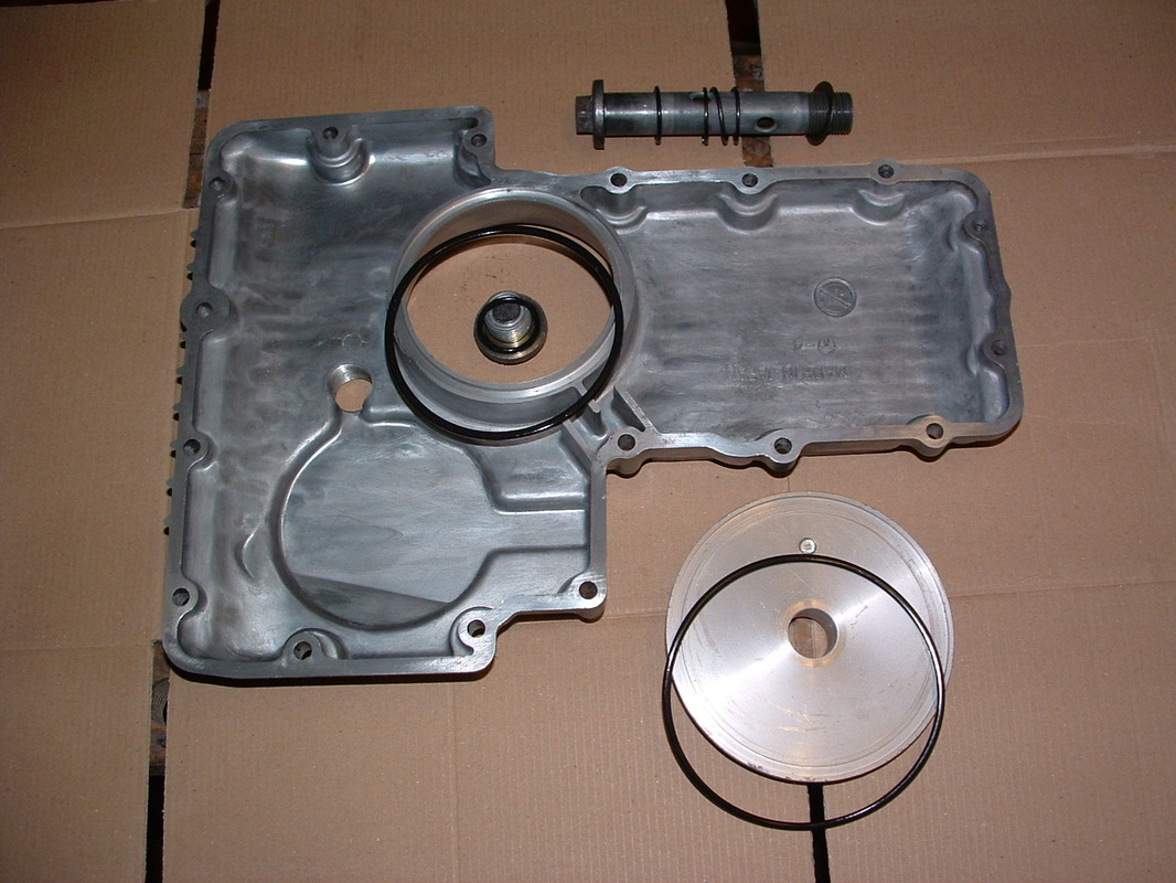
Oil Pan & O Rings
Now change this large O ring and the small one on the head of the sump drain plug. Then you have done all four.
The head of our drain plug was rounded off and filed for a flat spanner.
We will get a new one for the rebuild.
Make sure you get one with a magnetic core. This will catch any stray metal filings in your oil
The head of our drain plug was rounded off and filed for a flat spanner.
We will get a new one for the rebuild.
Make sure you get one with a magnetic core. This will catch any stray metal filings in your oil
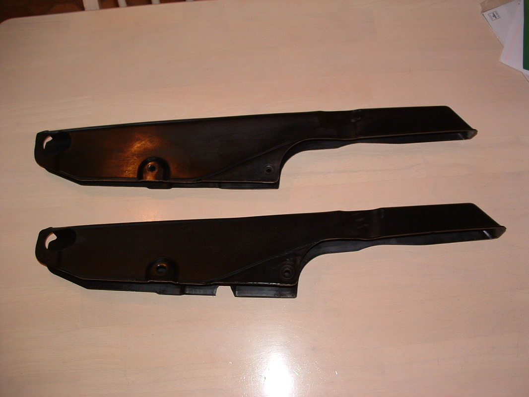
New Chain Guards - available here
You can get a new Z1-R chain guard from our Cool Parts page if you need one.
Our 1978 original got a bit chewed up by the tyre on the inner edge.
So we are going to fit one of ours to improve things.
They are an exact copy so they fit straight on.
Our 1978 original got a bit chewed up by the tyre on the inner edge.
So we are going to fit one of ours to improve things.
They are an exact copy so they fit straight on.
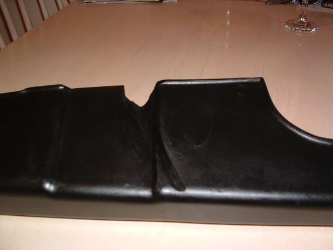
Rear Tyre contact marks
You would be surprised how common this kind of damage is.
The inner side of the chain guard is held in place between three brackets on the swinging arm - to stop it contacting the rear tyre.
The inner side of the chain guard is held in place between three brackets on the swinging arm - to stop it contacting the rear tyre.
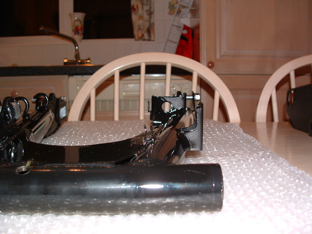
Inner chain guard brackets
The inner edge of the chain guard must be fitted to go in between the two front brackets shown here.
At the back of the bike it locates inside the U shaped retainer you can see.
The next image shows how it will look when correctly located.
At the back of the bike it locates inside the U shaped retainer you can see.
The next image shows how it will look when correctly located.
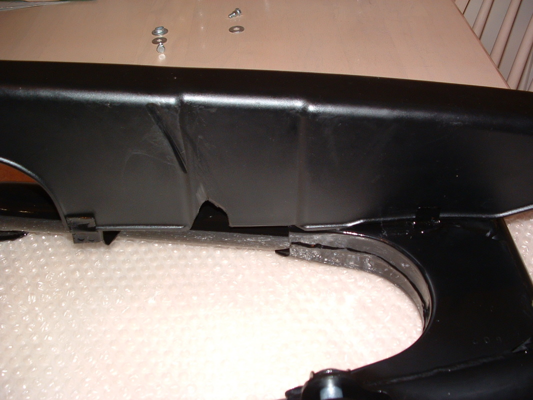
Retainer Brackets fitted correctly
This is what you should see when the chain guard is located correctly.
The other side will line up with the two M6 bolt holes.
Take a good look before the guard goes in and feel for this shape with your hand.
The frame will be in the way - which is why a lot of guys get this wrong.
The other side will line up with the two M6 bolt holes.
Take a good look before the guard goes in and feel for this shape with your hand.
The frame will be in the way - which is why a lot of guys get this wrong.
Chain Guard fittings
The rear fitting has a 20mm plain washer and a shouldered bolt.
The front fitting has a spacer washer fitted inside the guard, and an M6 x 18mm bolt with plain head to hold it on. The external plain washer is also 20mm
These correct fittings rarely survive as the chain guard will have been on and off for lubing and chain replacement over the years.
The front fitting has a spacer washer fitted inside the guard, and an M6 x 18mm bolt with plain head to hold it on. The external plain washer is also 20mm
These correct fittings rarely survive as the chain guard will have been on and off for lubing and chain replacement over the years.

Swinging Arm with fittings
The swinging arm is ready to go back onto the bike now.
Here it is with all the fittings ready to attach.
The pivot bolt goes inside the tube to the right of the arm.
This sits inside two roller bearings.
The pivot bolt is zinc plated but it has a chromed nut which goes to the left of the machine (chain side).
Here it is with all the fittings ready to attach.
The pivot bolt goes inside the tube to the right of the arm.
This sits inside two roller bearings.
The pivot bolt is zinc plated but it has a chromed nut which goes to the left of the machine (chain side).
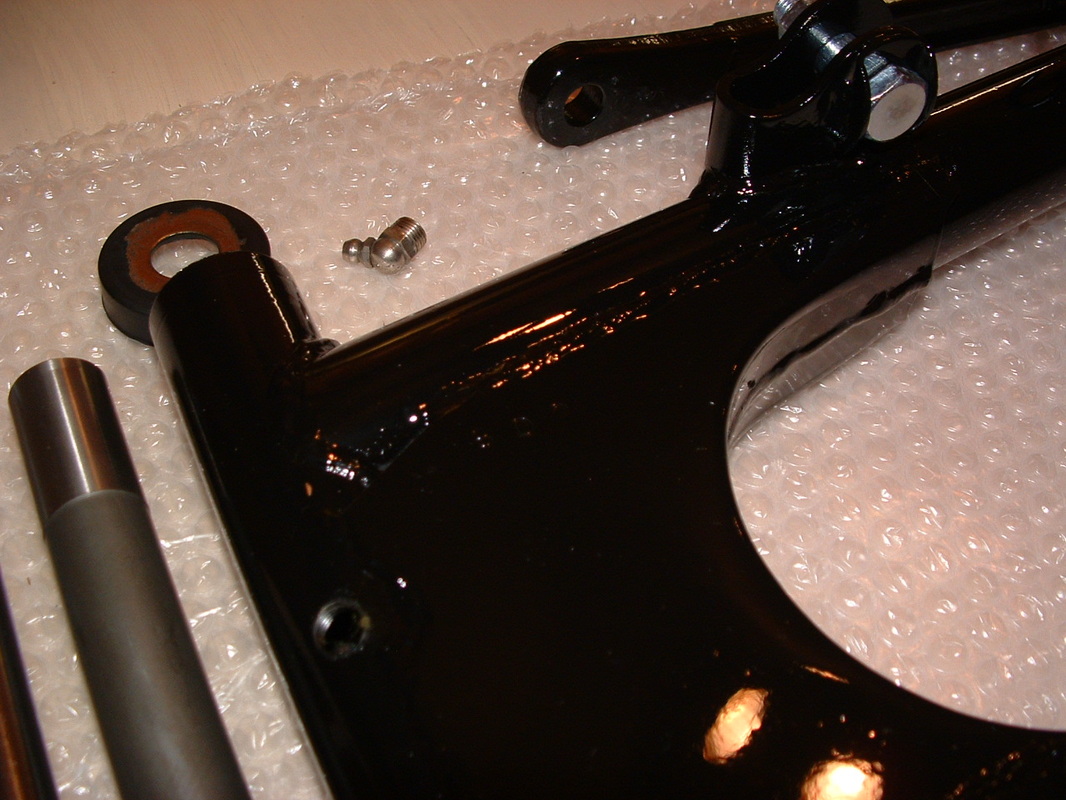
Swinging Arm date code
The swinging arm has a date code stamped into it.
You can just make it out here.
Restorers look for this as a reliable way to tell if a bike is genuine.
Lack of wear on the pivot tube is another sign of low mileage.
Remember to re-fit the grease nipple and get plenty of grease inside BEFORE you offer up the swinging arm to the bike.
You can just make it out here.
Restorers look for this as a reliable way to tell if a bike is genuine.
Lack of wear on the pivot tube is another sign of low mileage.
Remember to re-fit the grease nipple and get plenty of grease inside BEFORE you offer up the swinging arm to the bike.
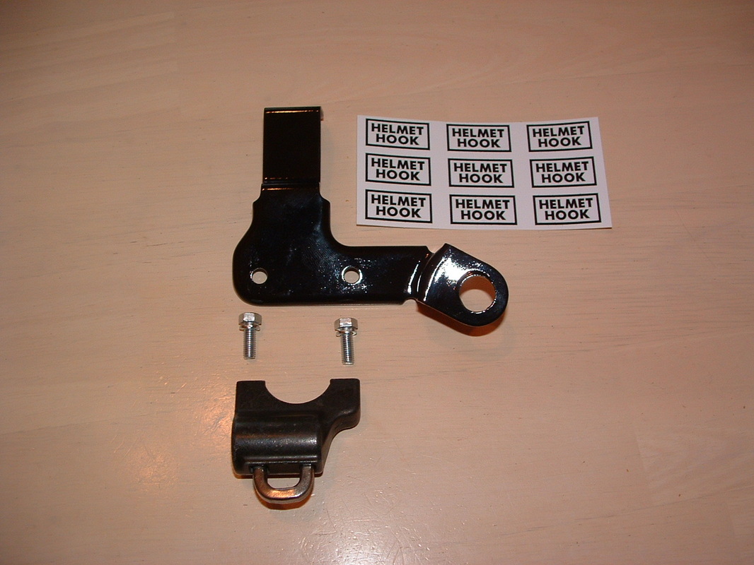
Helmet Lock components
The helmet lock bracket is attached between the right rear shock absorber mount and the upper rear frame tube. You need these two 8mm head bolts with captive lock washers to hold it together.
We have reproduced the original HELMET HOOK decal if you need one of those for your bike. You can get them on the Cool Parts page above.
We have reproduced the original HELMET HOOK decal if you need one of those for your bike. You can get them on the Cool Parts page above.

Helmet Lock assembled
The barrel must be installed with key hole facing left - or the bracket will prevent access. Earlier models used the seat lock to secure the helmet hooks.
This was another Z1-R upgrade feature.
Because the bracket is not part of the frame the assembly often went missing over the years and is now a rare find. The key number should be visible by the key hole if the part is genuine.
This was another Z1-R upgrade feature.
Because the bracket is not part of the frame the assembly often went missing over the years and is now a rare find. The key number should be visible by the key hole if the part is genuine.
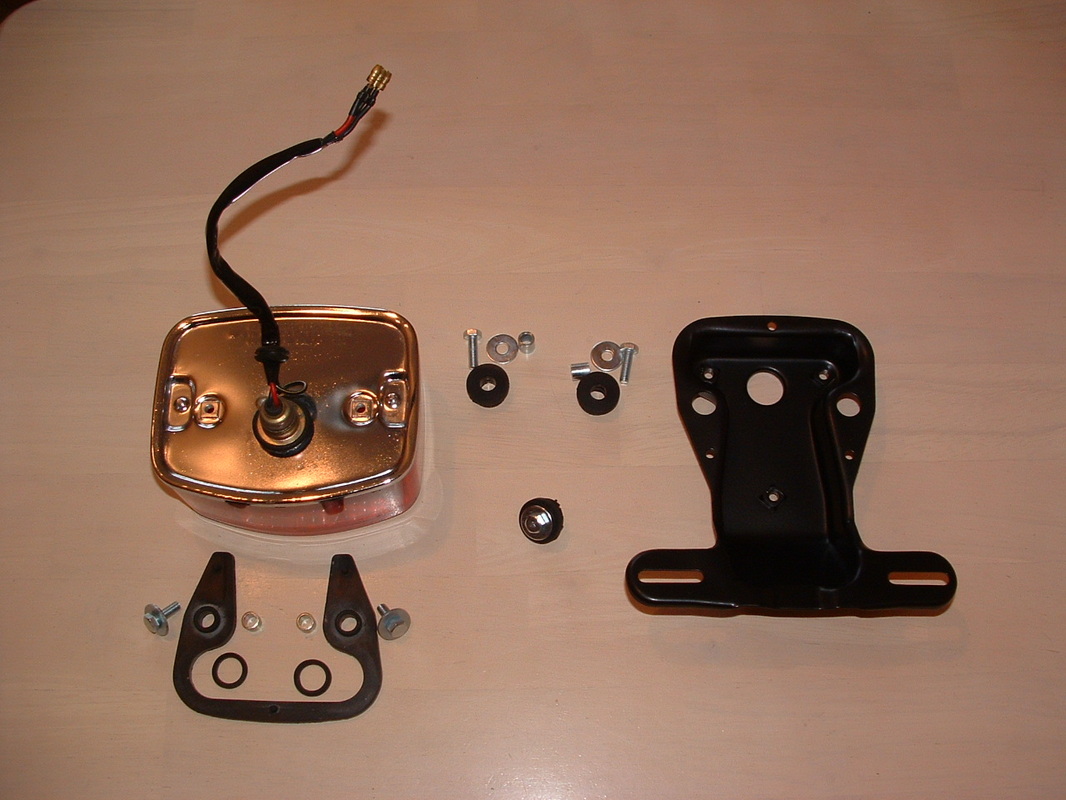
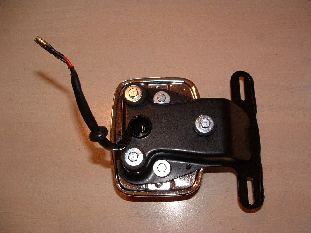
Stop Lamp & Bracket
The stop lamp has cleaned up well.
The 1978 chrome finish looks great and the wiring is intact.
The bracket is finished in satin black and the U shaped rubber goes between the two pieces to reduce vibration.
You can see all the correct bolts, damper rubbers and collars here.
The 1978 chrome finish looks great and the wiring is intact.
The bracket is finished in satin black and the U shaped rubber goes between the two pieces to reduce vibration.
You can see all the correct bolts, damper rubbers and collars here.
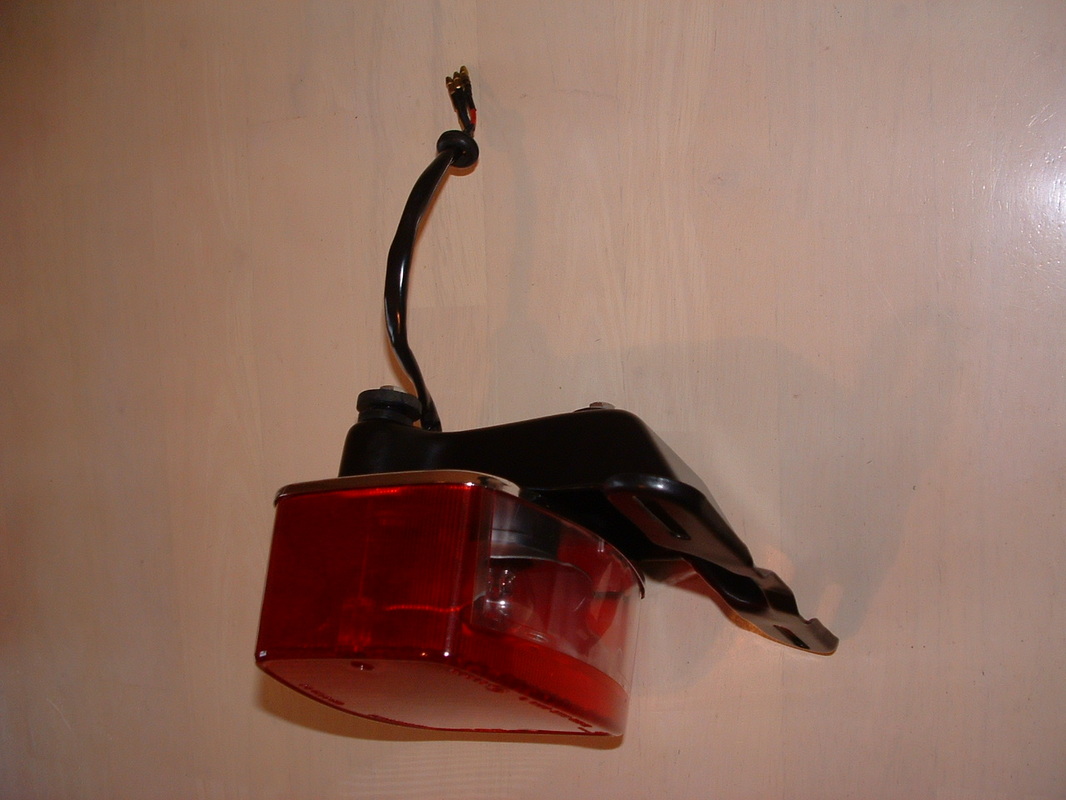
Stop Lamp & Bracket assembled
The bracket goes onto the lamp like this.
There should be a grommet on the wiring to prevent damage as it enters the frame space.
All the brass loom connectors will be cleaned and petroleum jelly applied - to give good contacts and prevent corrosion.
There should be a grommet on the wiring to prevent damage as it enters the frame space.
All the brass loom connectors will be cleaned and petroleum jelly applied - to give good contacts and prevent corrosion.
Licence Plate illumination
The underside of the lens is clear.
This acts to illuminate the licence plate.
The three damper rubbers & collars at the rear will need to go back onto the frame - BEFORE this assembly is re-fitted.
This unit can now be stored away ready for the rebuild.
This acts to illuminate the licence plate.
The three damper rubbers & collars at the rear will need to go back onto the frame - BEFORE this assembly is re-fitted.
This unit can now be stored away ready for the rebuild.
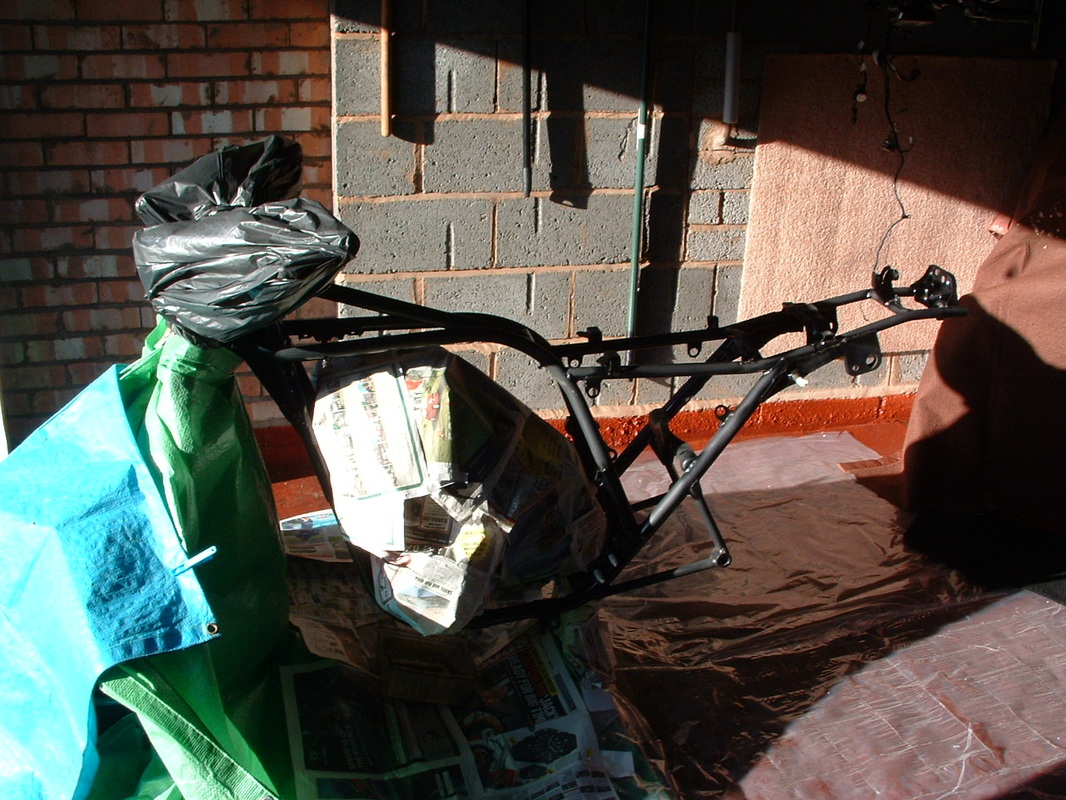
Frame masked off for painting.
The frame is in nice condition but will get a coat of paint to freshen it up now.
Otherwise all the re-finished brackets and fasteners will make it look tired after three decades.
The original finish was cellulose spray paint over metal.
We are going to copy that but use a gloss finish.
.
Otherwise all the re-finished brackets and fasteners will make it look tired after three decades.
The original finish was cellulose spray paint over metal.
We are going to copy that but use a gloss finish.
.
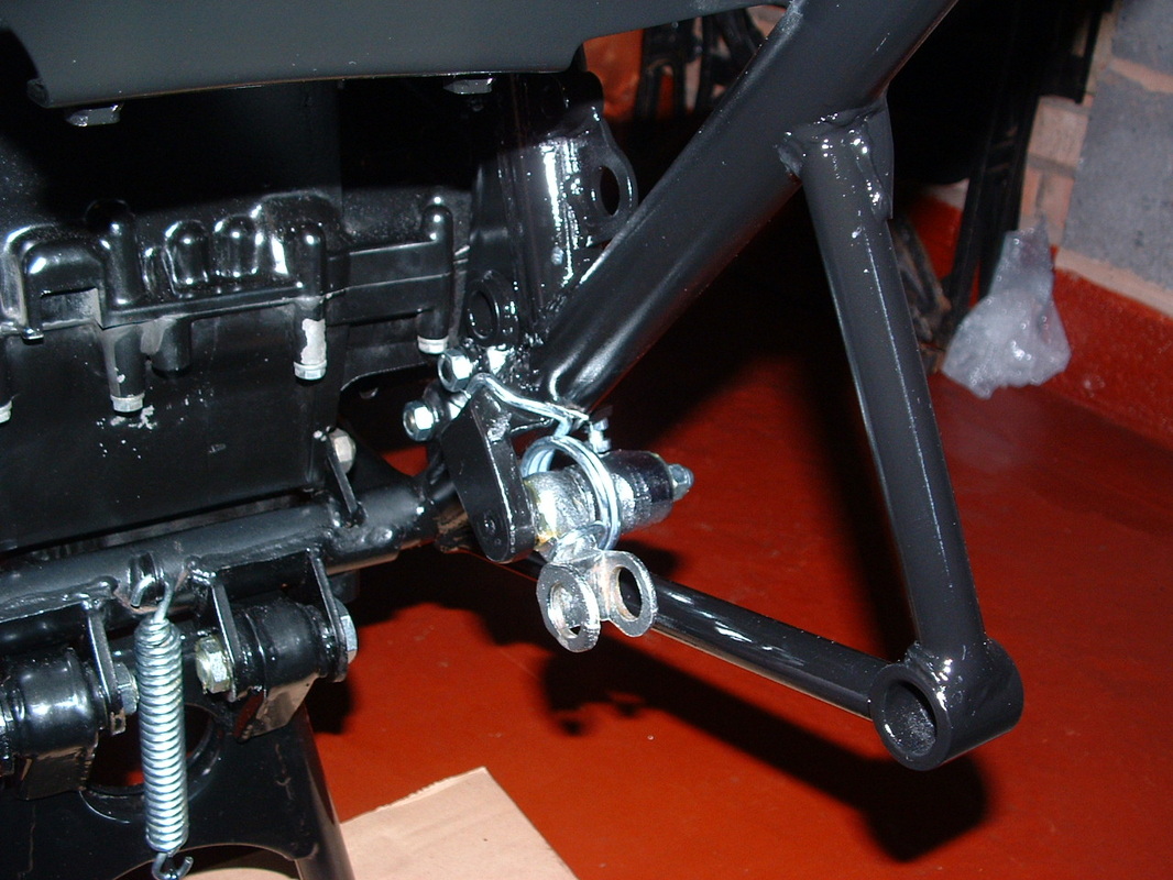
Re-fitted Brake Pedal & Spring
Now the frame has hardened the brake pedal and spring need to go back on.
Do this whilst the swinging arm is out of the way - for access.
Hook the spring over the frame and then use a wire puller to flip the other end over the brake pedal.
.
Do this whilst the swinging arm is out of the way - for access.
Hook the spring over the frame and then use a wire puller to flip the other end over the brake pedal.
.
Swinging Arm & Chain re-fitted
The endless chain MUST go on now - before the swinging arm goes in.
Loop it up out of the way like this - for protection - and to make space for the rear wheel and sprocket which are added next.
.
o
Loop it up out of the way like this - for protection - and to make space for the rear wheel and sprocket which are added next.
.
o
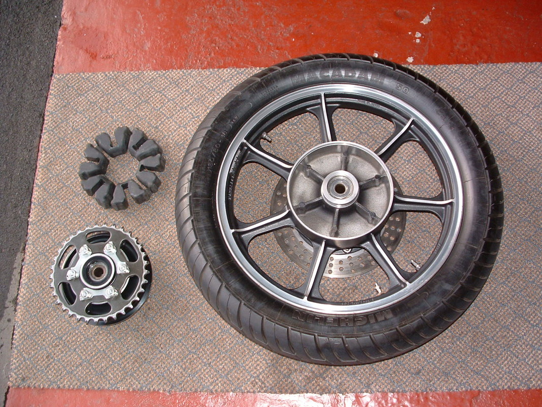
Rear Wheel and Sprocket
The rear wheel, sprocket and cush drive have been cleaned and inspected.
Grease the bearings before re-fitting to the swinging arm.
The original Z1-R rear sprocket was finished in this olive drab colour - unlike most Kawasakis at the time.
.
Grease the bearings before re-fitting to the swinging arm.
The original Z1-R rear sprocket was finished in this olive drab colour - unlike most Kawasakis at the time.
.
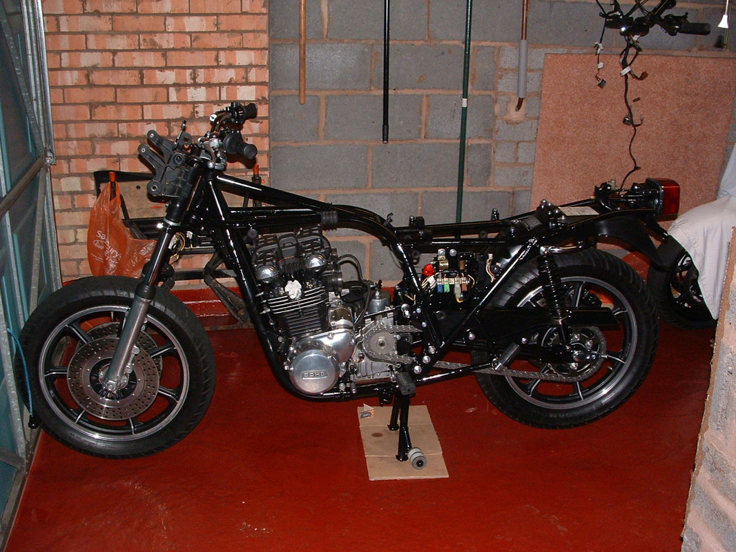
Back On Two Wheels Again
Here is the rebuilt rear of the bike.
The inner and outer fenders are fitted, along with the new stop lamp bracket.
The original warning decals are still intact and tidy so they will stay to provide a little "patina" effect.
.
The inner and outer fenders are fitted, along with the new stop lamp bracket.
The original warning decals are still intact and tidy so they will stay to provide a little "patina" effect.
.
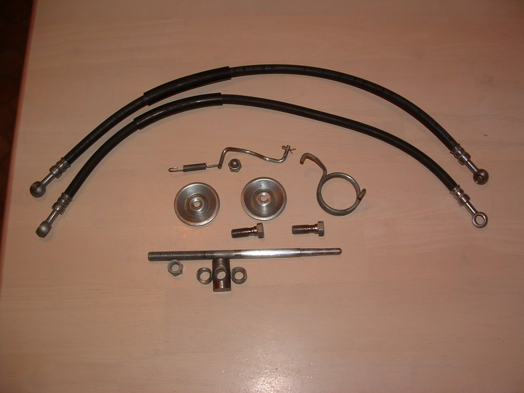
Rear Brake Master Cylinder & Switch
The brake rod MUST be fitted to the pedal BEFORE the master cylinder is added to the frame. It is fitted with two 13mm number 4 bolts like this.
Correct oil bolts are zinced with a 14mm head like this. The new part from Kawasaki is black with a different head. Don't forget to use new crush washers on the hoses.
The switch hook sits behind the footrest bracket.
.
Correct oil bolts are zinced with a 14mm head like this. The new part from Kawasaki is black with a different head. Don't forget to use new crush washers on the hoses.
The switch hook sits behind the footrest bracket.
.
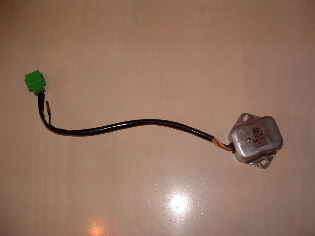
Original 1978 Regulator
The regulator fits to the right of the battery box - opposite the electric panel.
The connector is colour coded so that is easy.
This one has cleaned up well - even the factory sticker is still good.
You can test the voltage to the battery with the engine running to make sure the voltage is being controlled.
.
The connector is colour coded so that is easy.
This one has cleaned up well - even the factory sticker is still good.
You can test the voltage to the battery with the engine running to make sure the voltage is being controlled.
.
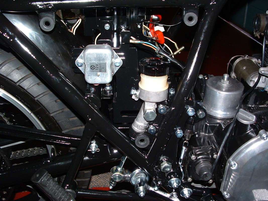
Rear Master Cylinder & Regulator fitted
Here is how the rear master cylinder links to the brake pedal.
You can also see where the stop lamp switch and regulator are fitted.
Our bike is getting new original brake hoses.
Remember to fit the brake pedal adjuster bolt with the head UNDER the bracket.
.
You can also see where the stop lamp switch and regulator are fitted.
Our bike is getting new original brake hoses.
Remember to fit the brake pedal adjuster bolt with the head UNDER the bracket.
.
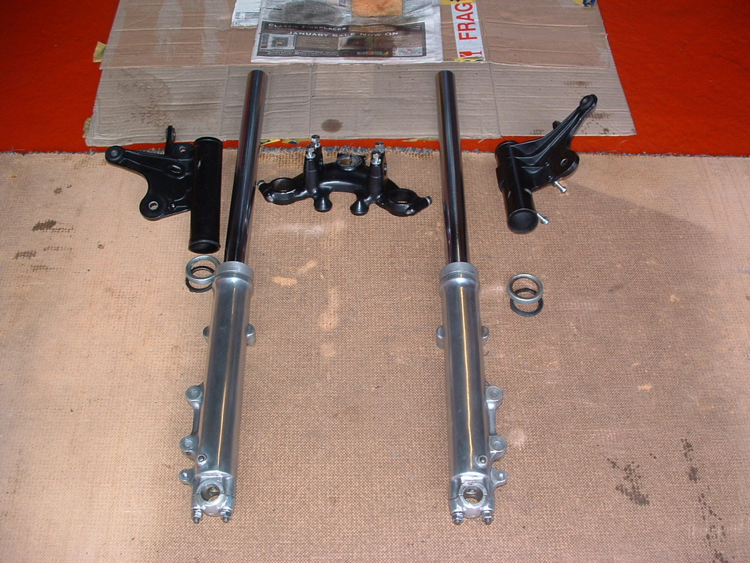
Forks after clean & service
The front forks have been washed out and the spring length checked against service limits. Make sure to fit the rubber gasket and zinc plated ring at the bottom of the headlamp ears where they meet the bottom yolk.
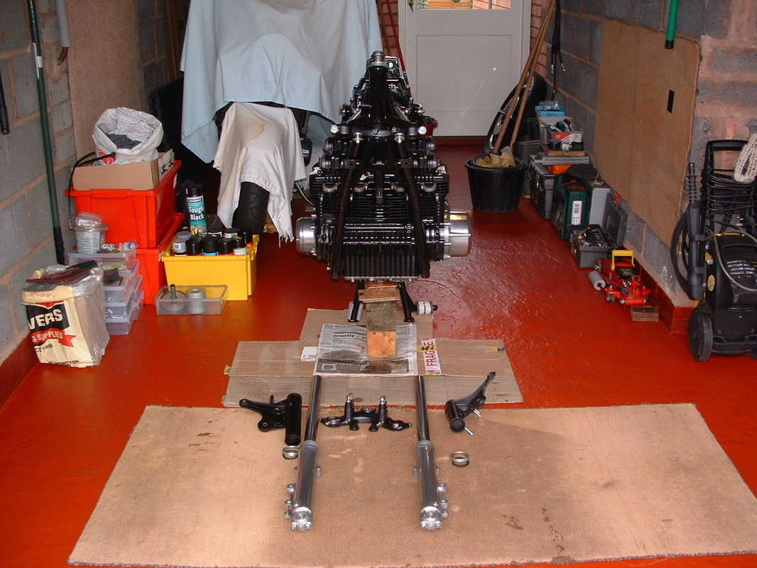
Head Bearings Greased & Yolks fitted
The head bearings have been checked and re-greased and the top and bottom yolks are back on the frame ready to slide the forks in.
The manual says to use SAE 15W fork oil and fill with 180-188 cc if the fork is completely drained. You can dip the oil from the top of the fork for a final test - it should be about 420 mm from top of leg.
.
The manual says to use SAE 15W fork oil and fill with 180-188 cc if the fork is completely drained. You can dip the oil from the top of the fork for a final test - it should be about 420 mm from top of leg.
.
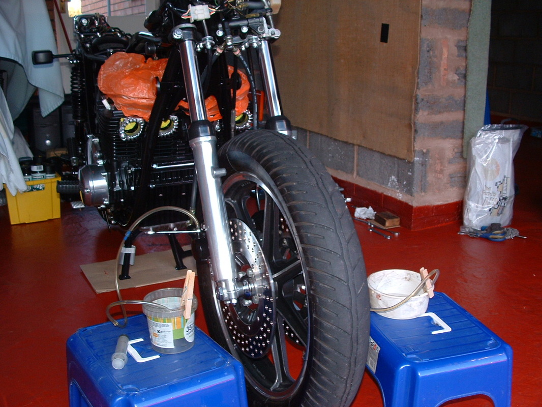
Rebuilt front end
Here is the front wheel back in place. It is safer with this to bear the weight of the engine and frame whilst we continue working.
The fork inner seals are holding fine and we are just waiting on new outer dust covers - don't use your forks on the road like this please !!
The fork lowers got a polish whilst they were removed.
.
The fork inner seals are holding fine and we are just waiting on new outer dust covers - don't use your forks on the road like this please !!
The fork lowers got a polish whilst they were removed.
.
Front Engine Mounting Bolt
The front engine to frame mounting is done with this long bolt.
It's quite visible at the front of the motor so it has been re-plated.
The special locking nut fits to the generator side.
.
It's quite visible at the front of the motor so it has been re-plated.
The special locking nut fits to the generator side.
.
Removable Engine bracket
The front offside engine bracket detaches for engine removal.
These two bolts hold it to the down tube. They are supposed to be different lengths like this.
.
These two bolts hold it to the down tube. They are supposed to be different lengths like this.
.

Bracket & Bolts Fitted
Fit the bracket with bolt heads facing out like this.
Then the long bolt can be threaded through & tightened.
.
Then the long bolt can be threaded through & tightened.
.
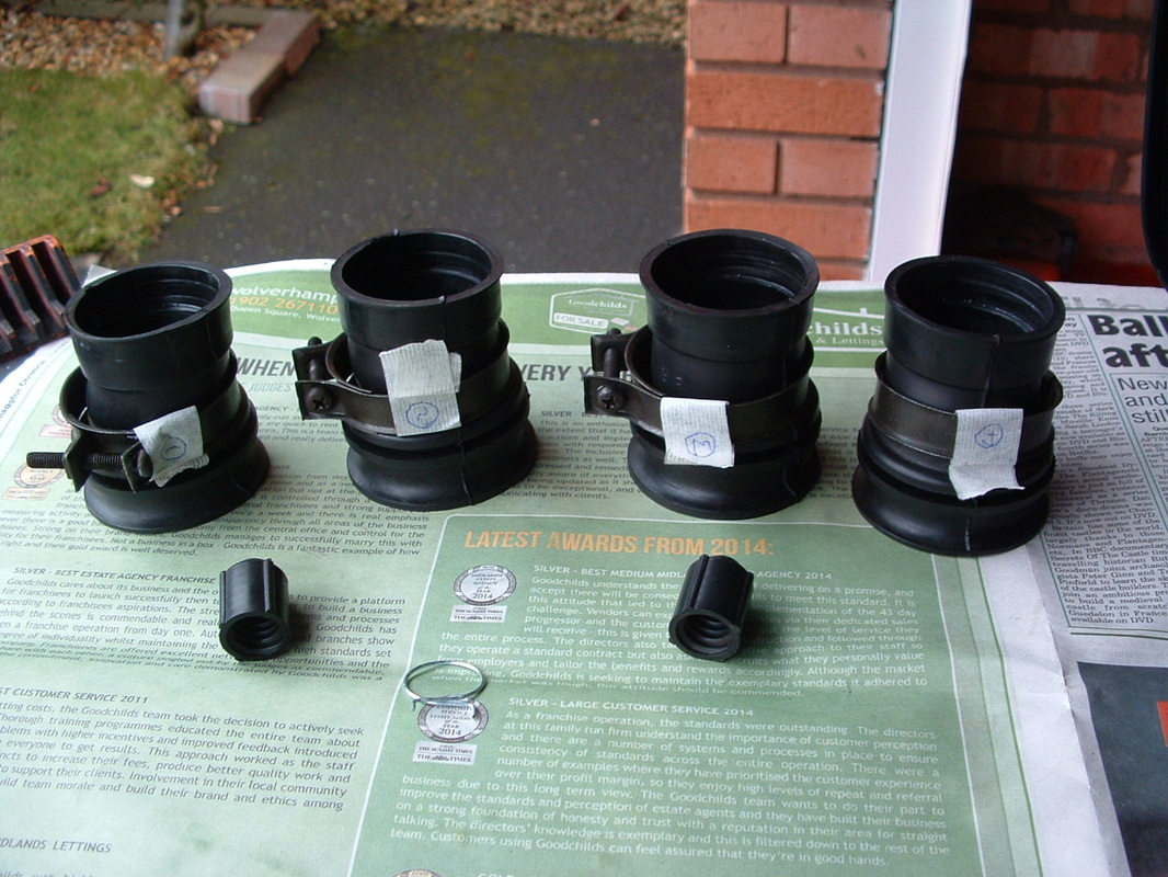
Airbox Rubbers & Drain Caps
The Airbox rubbers are marked up & L for number one cylinder or up and R for number four cylinder.
These two drain caps screw into the Airbox base.
.
These two drain caps screw into the Airbox base.
.
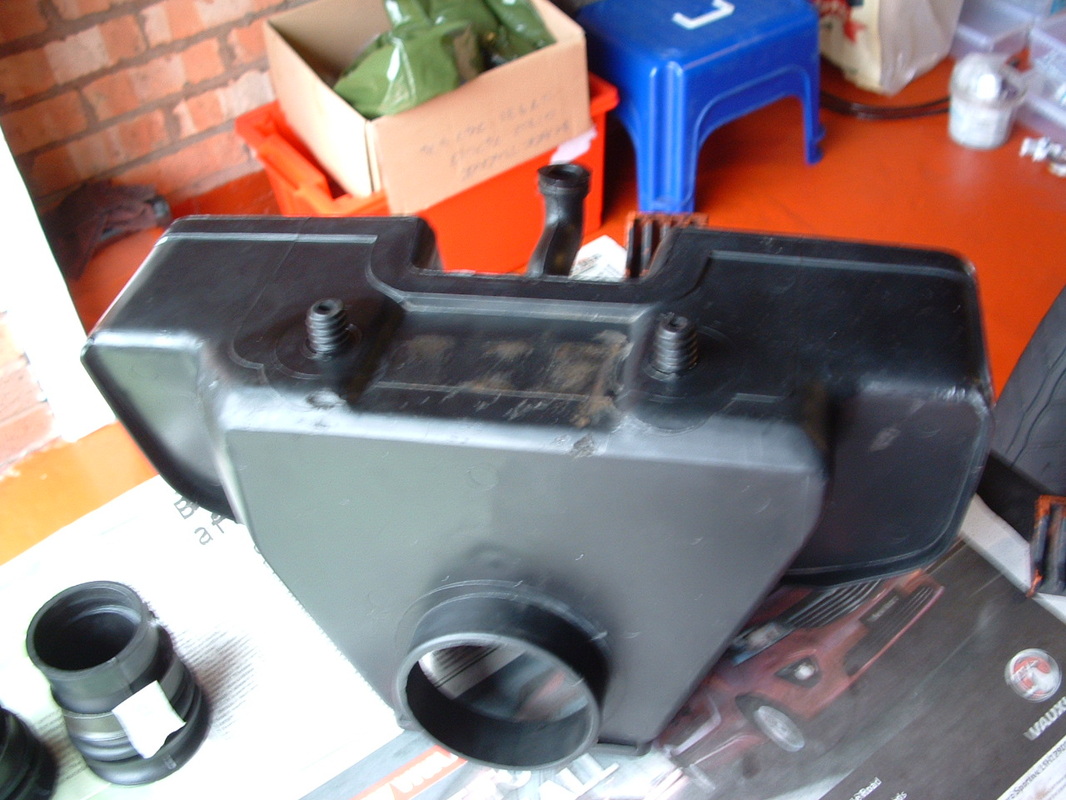
Drain Caps & PCV Tube
The drain caps are fitted here.
The PCV tube is visible at the front of the Airbox.
The large hole at rear is to take the silencer unit. These often got lost or removed in pursuit of performance.
.
The PCV tube is visible at the front of the Airbox.
The large hole at rear is to take the silencer unit. These often got lost or removed in pursuit of performance.
.
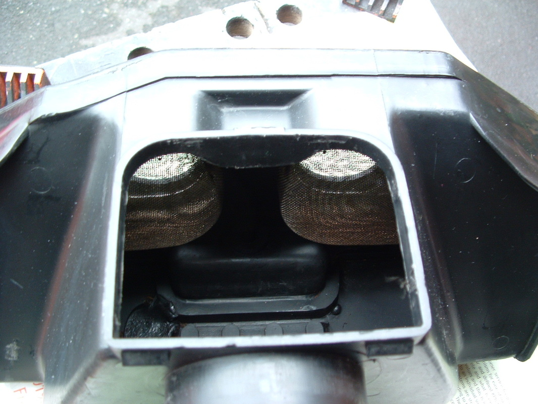
Inner Grilles Shown
These metal grilles are behind each hose.
You can fit the hoses without removing them.
.
You can fit the hoses without removing them.
.
 Carb Cleaning & Inspection
The carbs got taken down and cleaned out.
The brass jets were removed and washed out in thinners.
Check the needle valve for wear at this point.
Carb cleaner spray can now be injected through the various passages.
The slide clearance can be set manually if the bike was running poorly before the strip down.
The brass jets were removed and washed out in thinners.
Check the needle valve for wear at this point.
Carb cleaner spray can now be injected through the various passages.
The slide clearance can be set manually if the bike was running poorly before the strip down.
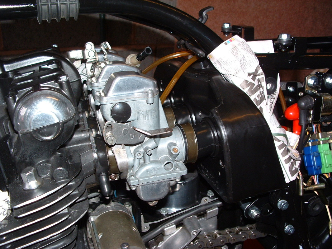
Re-fitted Carbs & Frame protection
The frame was masked for protection and the Airbox re-fitted.
You MUST do this before fitting the carbs.
.
You MUST do this before fitting the carbs.
.
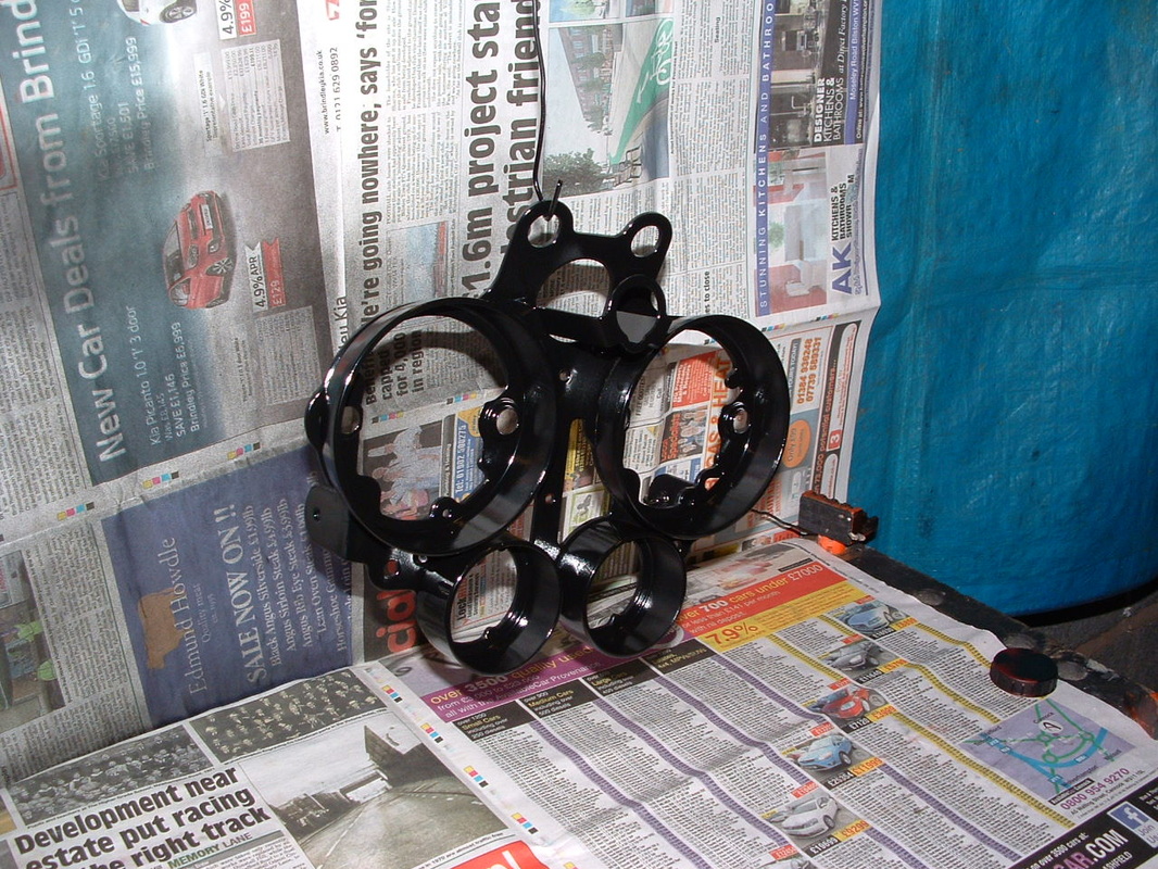
Meter Bracket
This bracket holds the meters.
The Z1-R has extra meters for fuel level and an ammeter.
Several rubber dampers are needed to protect the instruments.
.
The Z1-R has extra meters for fuel level and an ammeter.
Several rubber dampers are needed to protect the instruments.
.
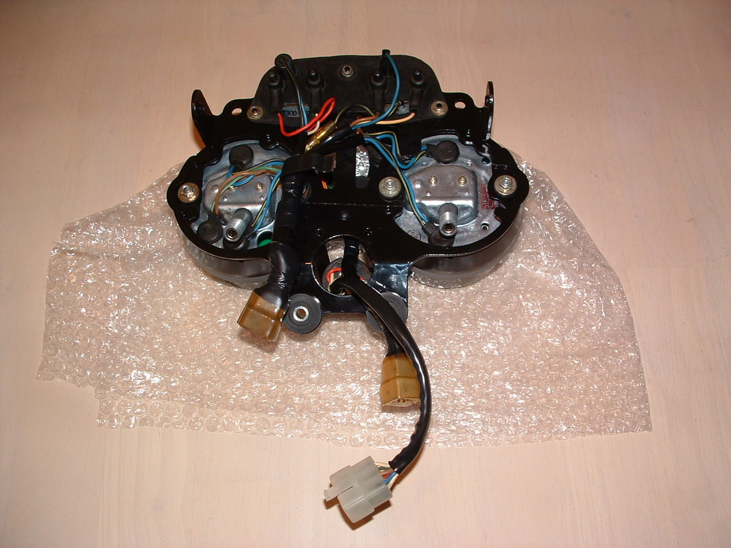
Re-assembled Meters
Here is the rebuilt unit ready to go back onto the machine.
Now is the time to check that all those little bulbs are still working.
.
Now is the time to check that all those little bulbs are still working.
.

Ammeter Testing
The ammeter can be tested like this.
Use an 8 watt bulb to protect the device during testing.
.
Use an 8 watt bulb to protect the device during testing.
.
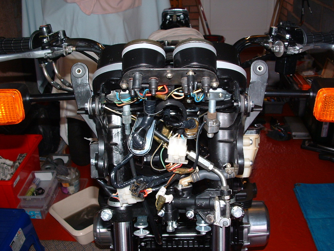
Meters Re-assembled
The meters are re-fitted to the bike, new silicon dampers will protect them from vibration.
The instrument cover goes on top of the fuel gauge and ammeter and just leaves a rectangle showing through.
The instrument cover goes on top of the fuel gauge and ammeter and just leaves a rectangle showing through.
Front Callipers for painting
The front callipers were stripped and prepared for re-painting.
.
.
Silver Parts masked off
Some parts should remain bright alloy with no paint.
These areas got cleaned up first - then masked off.
Before the painting started.
.
These areas got cleaned up first - then masked off.
Before the painting started.
.

Silver parts revealed and holder fitted
Here is an assembled calliper - you can see the bright finish on the areas which were masked off now. The large zinc plated disc is a holder plate for the rear brake pad. These all got cleaned up and re-plated.
The holder bolts to the fork leg - it should be this olive drab color - not black painted or bright zinc plated.
.
The holder bolts to the fork leg - it should be this olive drab color - not black painted or bright zinc plated.
.
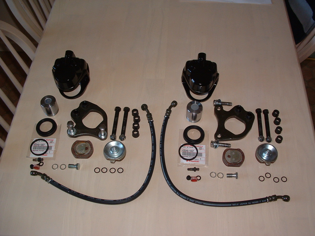
Front Brake components
We collected new brake hoses from Japan. There is no upper hydraulic hose on the Z1-R because the master cylinder is cable activated.
There is just a short pipe from the master cylinder to the fluid reservoir inside the fairing.
.
There is just a short pipe from the master cylinder to the fluid reservoir inside the fairing.
.
Bleeding front brakes
Now the front brakes can be bled to recover the pressure in the system. We did both sides in turn and then left this set up overnight - for any remaining air bubbles to be expelled the next day with a final bleed.
The callipers had new inner and outer seals, plus new O rings on the holder shafts.
.
The callipers had new inner and outer seals, plus new O rings on the holder shafts.
.
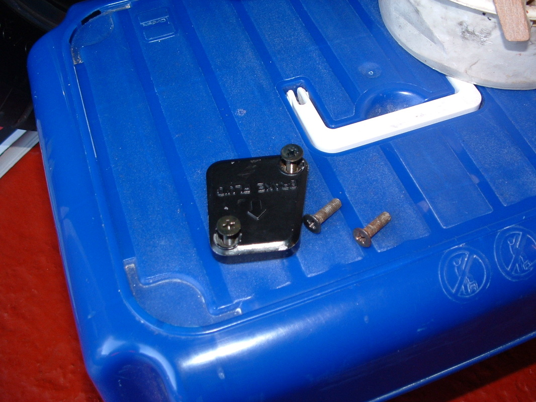
New Reservoir Cap screws
The screws which hold the fluid reservoir were past their best.
We got new ones from Kawasaki - in the correct finish.
You can see this cap inside the fairing on the left side.
.
We got new ones from Kawasaki - in the correct finish.
You can see this cap inside the fairing on the left side.
.
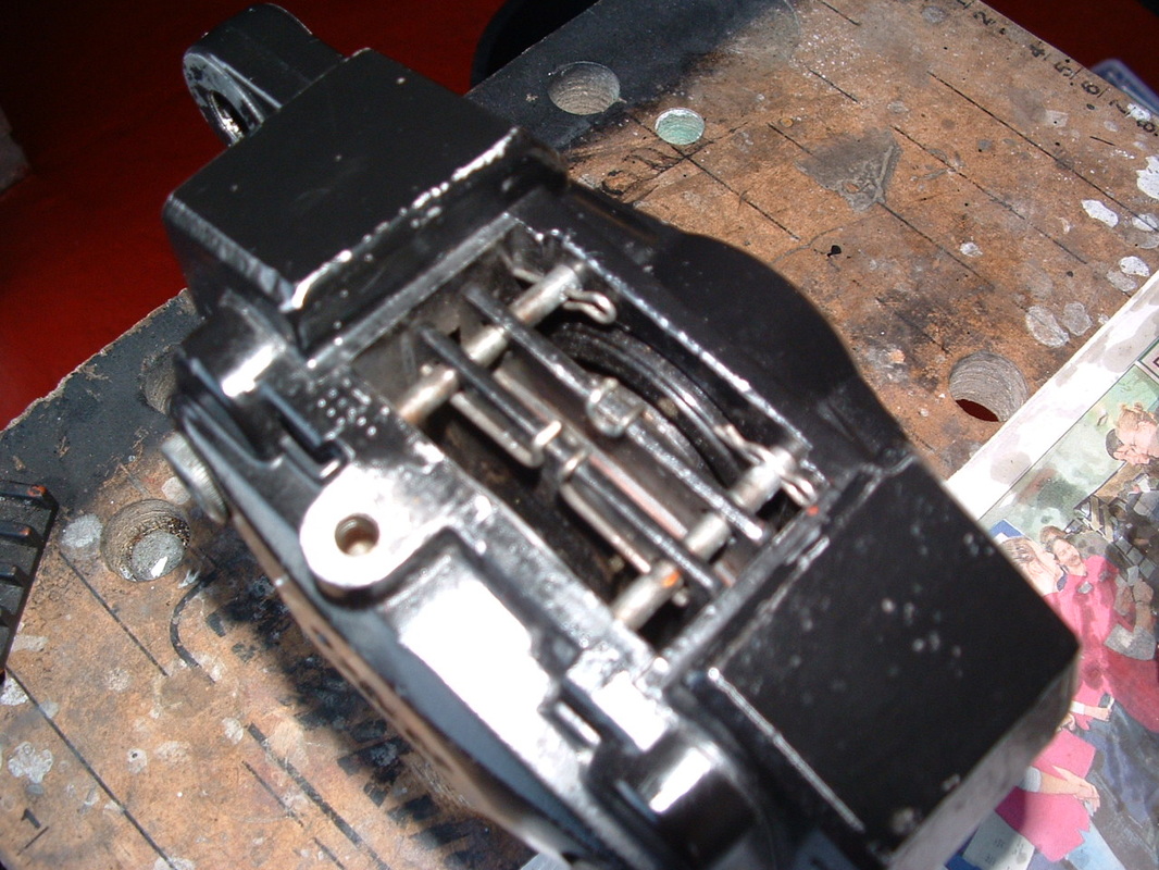
Rear Calliper Components
The rear calliper has pins and clips to hold the pads in place.
It has two pistons, not like the front which has one.
That is because this calliper is fixed and cannot move.
A plastic cover stops rain getting inside from the top.
.
It has two pistons, not like the front which has one.
That is because this calliper is fixed and cannot move.
A plastic cover stops rain getting inside from the top.
.
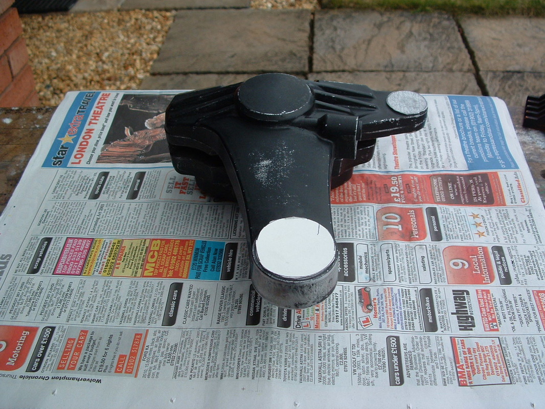
Masked off for Painting
The calliper is stripped and rubbed down ready for new paint.
We have masked off the areas which will stay as bright alloy.
Block the unions so no brake fluid can seep out to damage the new paint.
.
We have masked off the areas which will stay as bright alloy.
Block the unions so no brake fluid can seep out to damage the new paint.
.
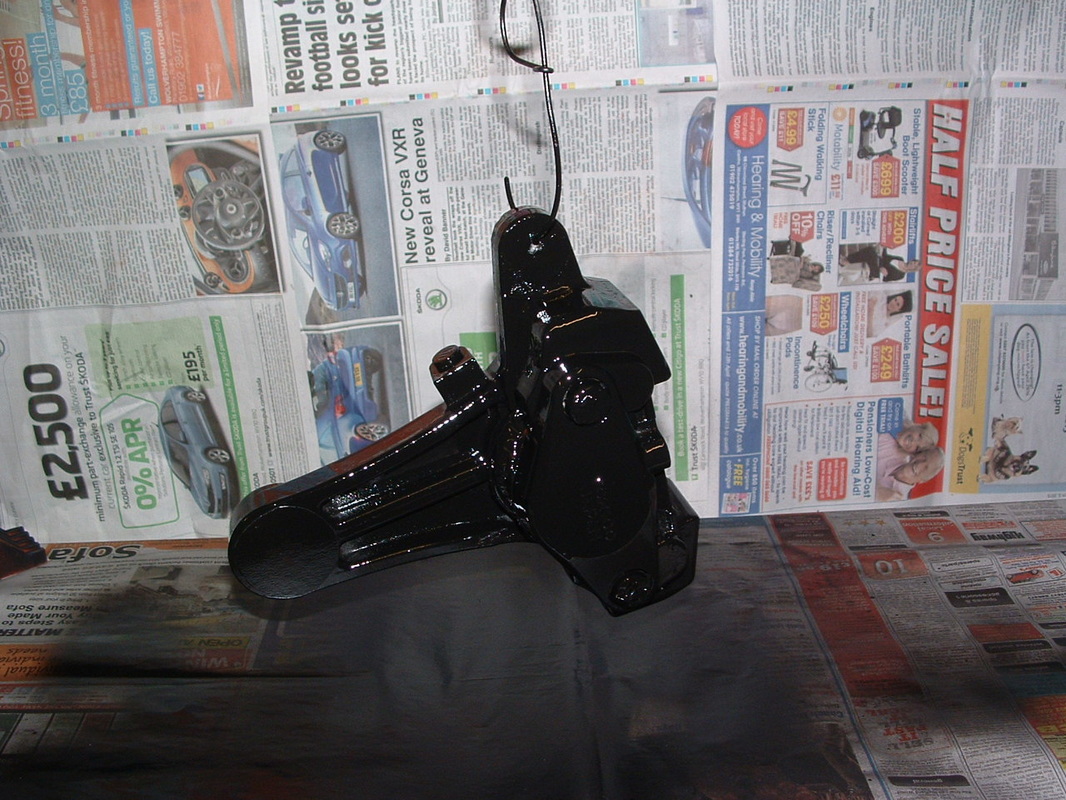
New Paint Finish
The calliper is sprayed underneath first.
Then it is hung up for the top edges to be sprayed.
.
Then it is hung up for the top edges to be sprayed.
.
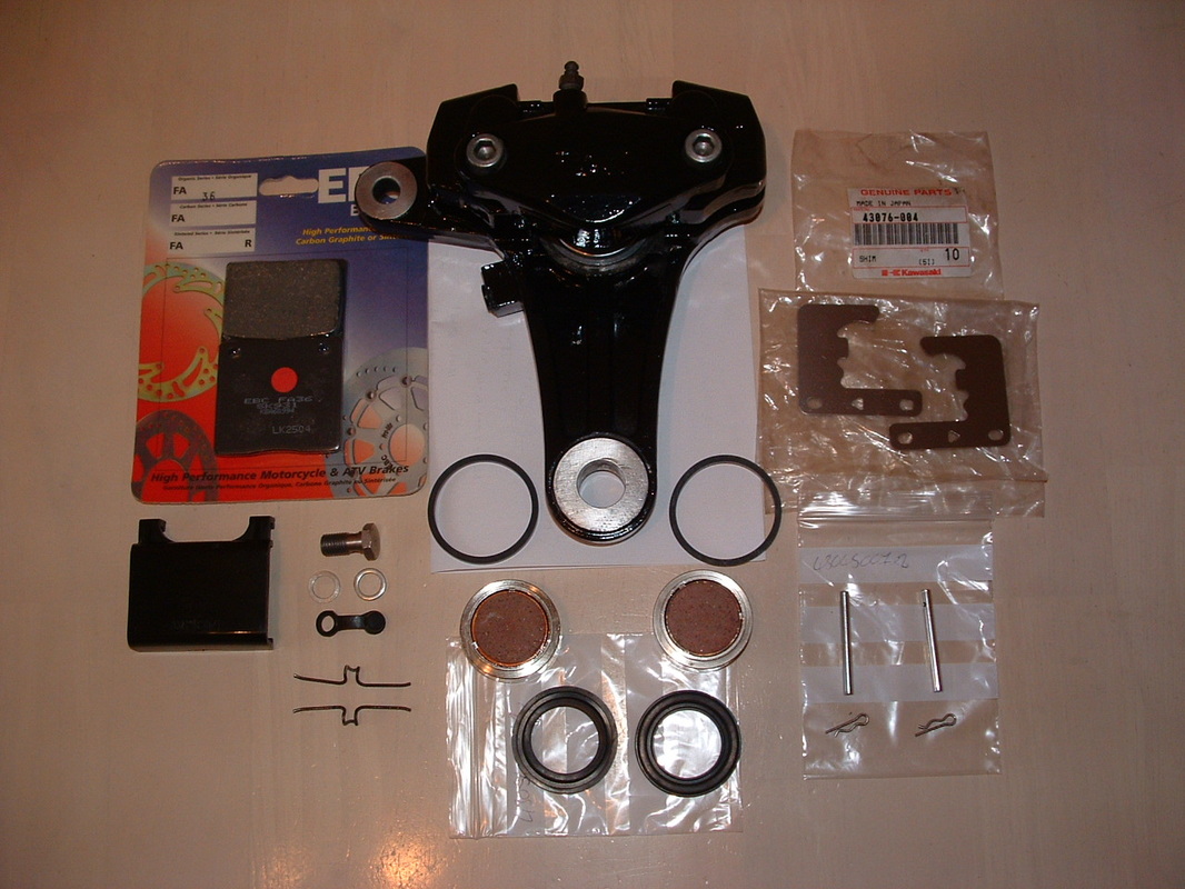
New Components for the Rebuild
Here are the components needed to restore the calliper.
You can buy a pair of rear pistons with seals from our Cool Parts page.
The rare factory shims are often missing or corroded away on these bikes.
We are fitting new pads and pins to hold them.
.
You can buy a pair of rear pistons with seals from our Cool Parts page.
The rare factory shims are often missing or corroded away on these bikes.
We are fitting new pads and pins to hold them.
.
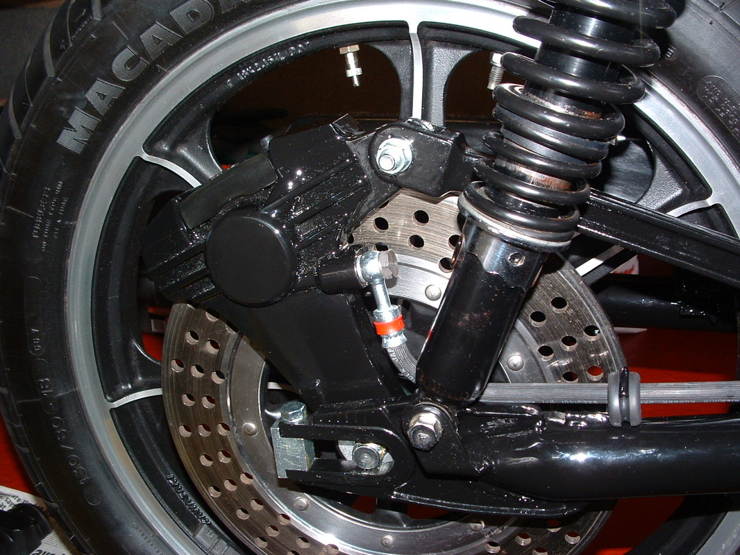
Re-fitted Rear Calliper
The calliper is attached to the torque arm again now.
The plastic cover is clipped back on to cover the pads.
Don't forget to loosen the torque arm nut -
before you adjust the drive chain tension !!
.
The plastic cover is clipped back on to cover the pads.
Don't forget to loosen the torque arm nut -
before you adjust the drive chain tension !!
.
 Tank Stripped To Metal
The new gas tank was chemically stripped back to bare metal.
This made sure there was no damage, corrosion or filler that we did not know about. Three layers of primer went on, before the base coat.
This made sure there was no damage, corrosion or filler that we did not know about. Three layers of primer went on, before the base coat.
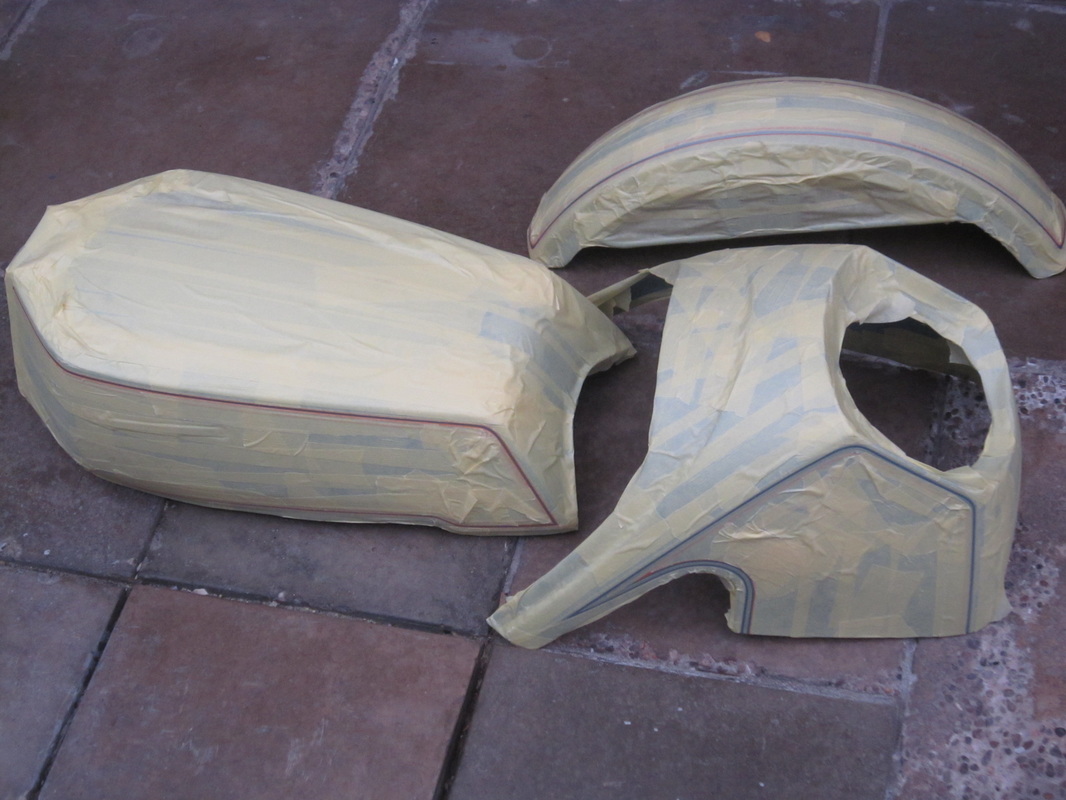 Masked For Striping
Templates were made to give correct pinstripe positions.
Then the panels were masked up ready for the stripes to be applied.
Original stripes were adhesive decals. On the tank they were lacquered, on the front fender they were stuck on in four sections with overlap at each corner.
Then the panels were masked up ready for the stripes to be applied.
Original stripes were adhesive decals. On the tank they were lacquered, on the front fender they were stuck on in four sections with overlap at each corner.
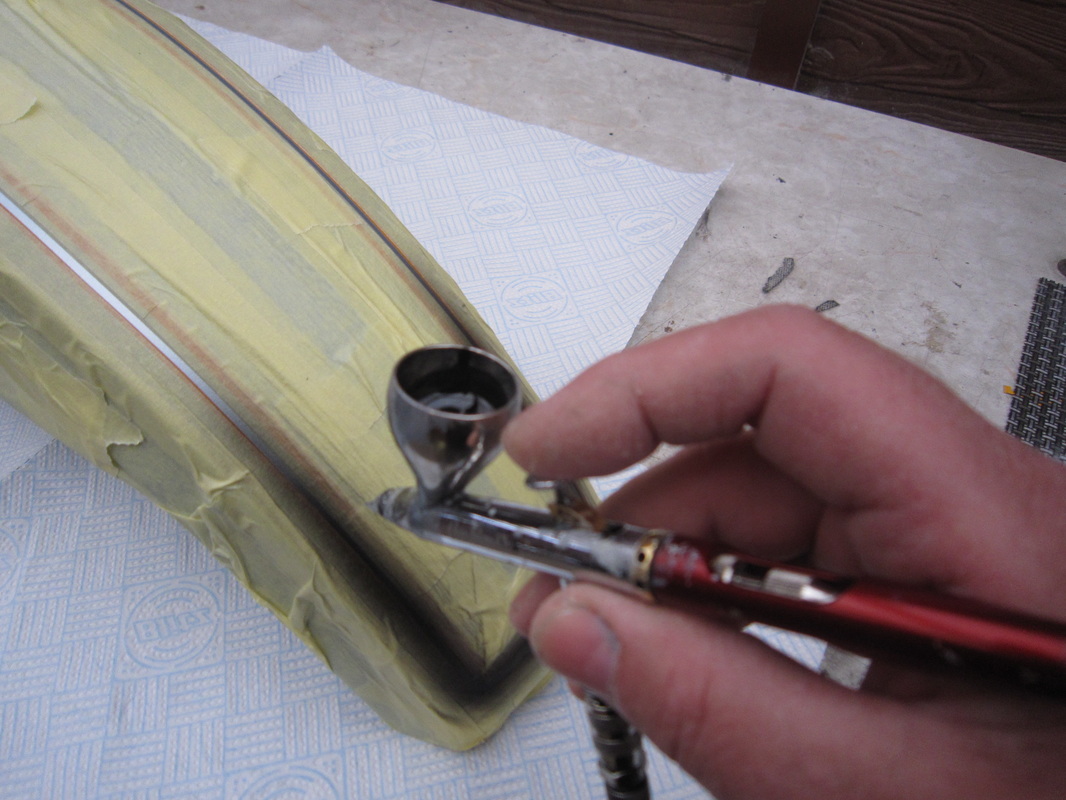 Air Brushed Stripes
The new stripes are applied with an airbrush.
This gives no overlap at the fender edges.
The gas tank and fender get the same treatment.
All the panels are then lacquered after the stripes are in place - to protect them from wear and any spilled gas.
This gives no overlap at the fender edges.
The gas tank and fender get the same treatment.
All the panels are then lacquered after the stripes are in place - to protect them from wear and any spilled gas.
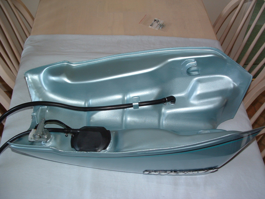 Gas Tank Fittings Restored
The underside of the tank also got returned to the correct factory finish.
The low tank has an extra overflow pipe to drain the recessed fuel cap.
The Fuel gauge sender unit has electrical connections and a further overflow pipe.
The low tank has an extra overflow pipe to drain the recessed fuel cap.
The Fuel gauge sender unit has electrical connections and a further overflow pipe.
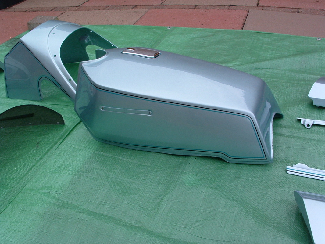 Low Profile Tank Repainted
This original 1978 low profile gas tank came as a spare with the bike.
It looks more elegant than the large touring tank which was fitted.
Although the distance between refuelling will now be reduced.
The tank is so low that the gas cap had to be offset to clear the frame.
It looks more elegant than the large touring tank which was fitted.
Although the distance between refuelling will now be reduced.
The tank is so low that the gas cap had to be offset to clear the frame.
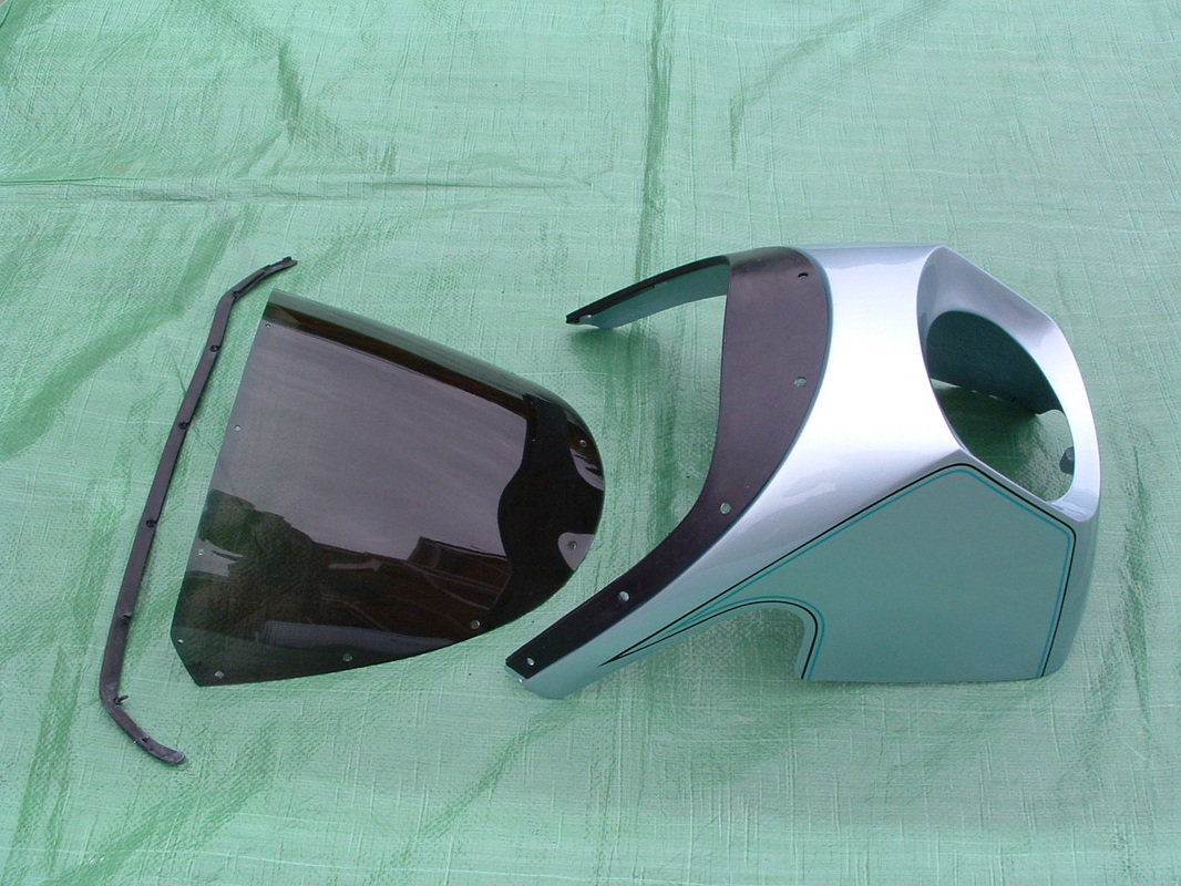 Fairing & Screen
The fairing is repainted now. Two rubber trims attach to the screen. The rear trim is held by protruding plugs and the front trim is held by olive coloured bolts and black plastic nuts.
TIP - do not over tighten the screen bolts - or the fairing and screen may get cracked from the stress.
TIP - do not over tighten the screen bolts - or the fairing and screen may get cracked from the stress.
 Fairing Brackets & Dampers
Here is the internal detail & fittings for the fairing.
The brackets will be hidden by the black inner fairing trim.
TIP - brass internal threads are fixed to the fairing. Apply grease or the zinc bolts can get stuck with corrosion.
The brackets will be hidden by the black inner fairing trim.
TIP - brass internal threads are fixed to the fairing. Apply grease or the zinc bolts can get stuck with corrosion.
 Original Paintwork To Match
The tail unit and side trims all came in good condition.
So they will just be polished and the emblems were touched in where they had lost any paint.
The newly painted panels are an exact match for this colour.
So they will just be polished and the emblems were touched in where they had lost any paint.
The newly painted panels are an exact match for this colour.
Power Chamber for Painting
The outer header pipes are welded to the collector box.
Kawasaki called it a "Power Chamber" on this bike.
We masked the chrome to protect it whilst the old paint was removed and the chamber given a good clean up.
Kawasaki called it a "Power Chamber" on this bike.
We masked the chrome to protect it whilst the old paint was removed and the chamber given a good clean up.
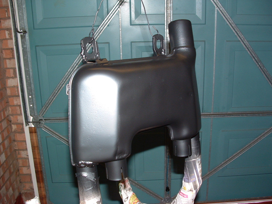
Re-finished Power Chamber
Here is the re-finished unit.
High temperature paint is needed here.
High temperature paint is needed here.

Exhaust Fasteners re-finished
The exhaust fasteners all got re-zinc plated or re-painted in the correct black finish.
The rubbers to the left will hold the chamber to the frame.
The rubbers to the left will hold the chamber to the frame.
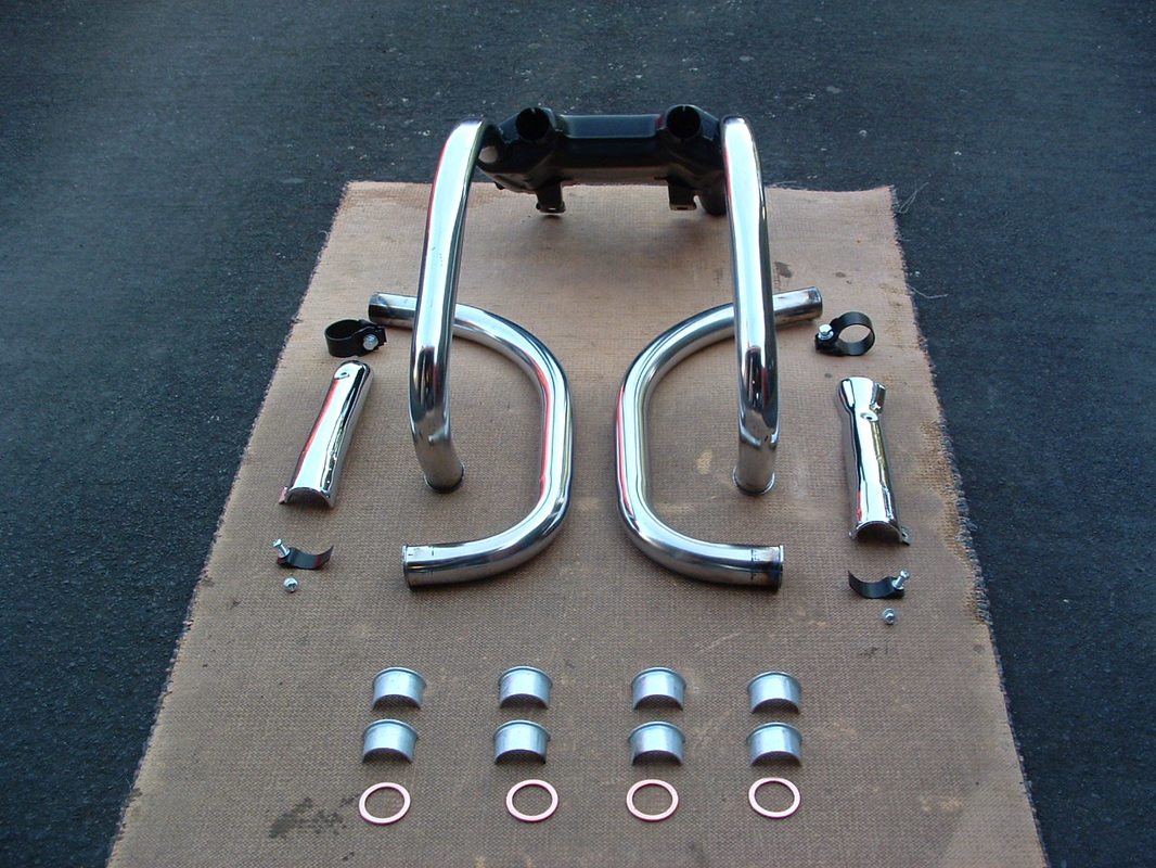
Exhaust Components
Here is the front and middle of the system - with all the fastenings - ready to go back onto the bike.
These heat shields have been chrome plated, but the originals were in a black finish - similar to the collector box.
These heat shields have been chrome plated, but the originals were in a black finish - similar to the collector box.
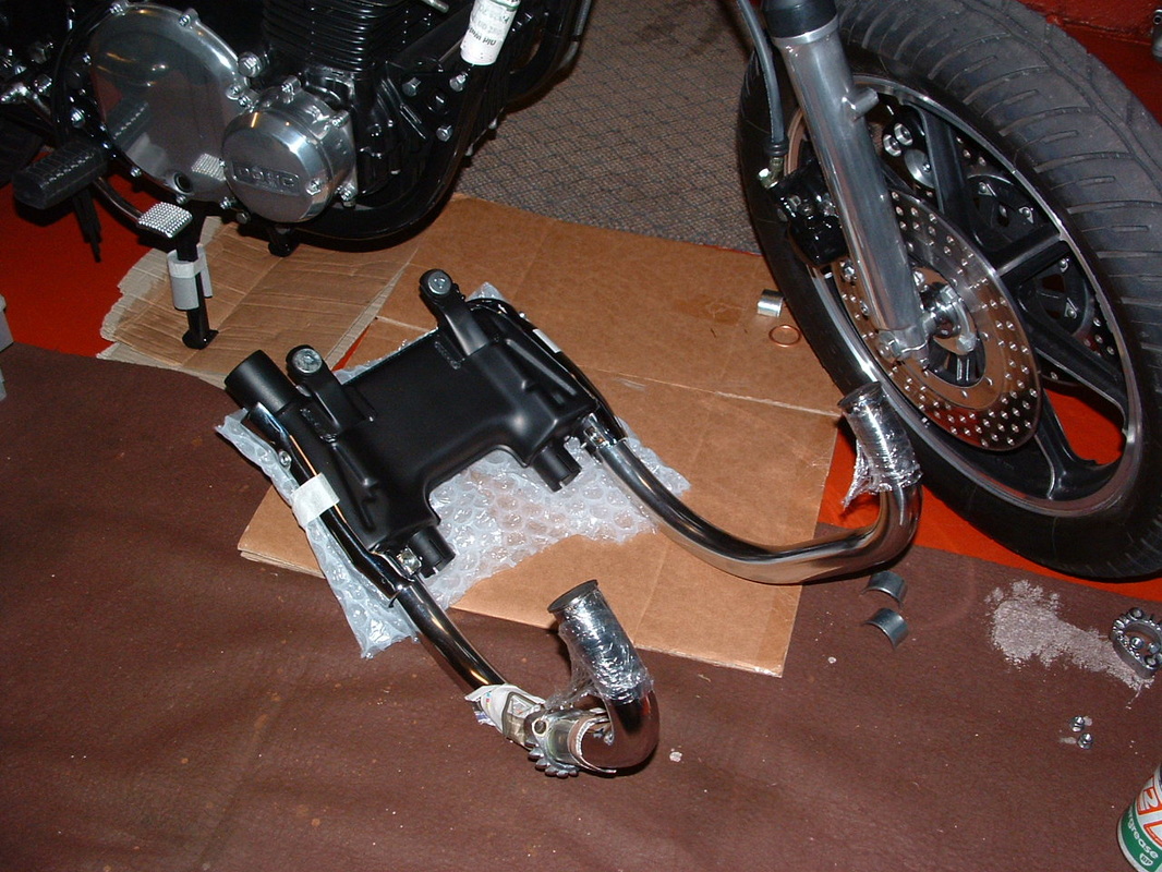
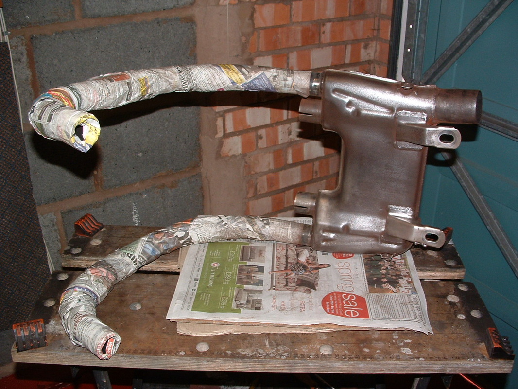
Front Pipe Assembly
The heat shields MUST be attached to the chamber BEFORE it is fitted to the bike. We used bubble wrap and cling film to protect the finish on header pipes and the painted chamber whilst they were being fitted.
Newspaper wrapped round the frame tubes will stop the header pipes marking the frame.
Newspaper wrapped round the frame tubes will stop the header pipes marking the frame.
 Header Pipe Detail
The down pipes and power chamber are fitted now.
Ensure the front fender is removed or protected when the pipes are attached.
TIP - Do final tightening of all clamps AFTER the muffler is fitted.
Ensure the front fender is removed or protected when the pipes are attached.
TIP - Do final tightening of all clamps AFTER the muffler is fitted.

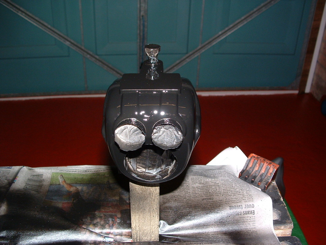
New Silencer & Seat Foam
To finish off the exhaust system we got a new muffler and bracket from Japan. This comes with the main stand stopper and a new silencer clamp.
The end cone will need the inner face painting black to match the original system.
The end cone will need the inner face painting black to match the original system.
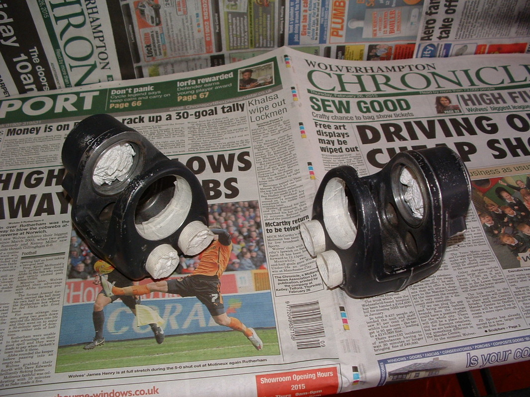
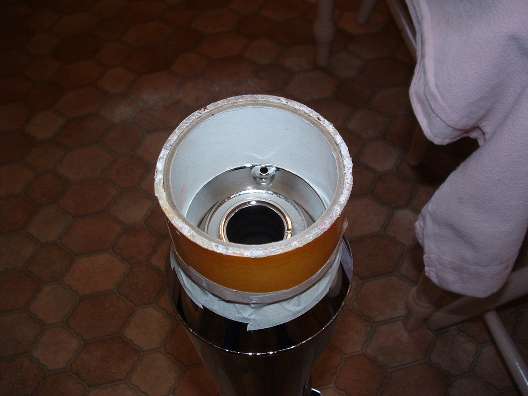 Silencer Masked For Painting
The silencer is masked up with a tube and tape.
All ready for the black heat resistant paint to be applied.
All ready for the black heat resistant paint to be applied.
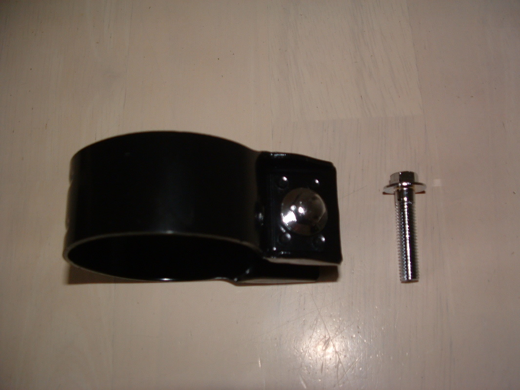 Silencer Clamp & Flanged Bolt
The silencer is attached to the power chamber with this clamp.
The special bolt is flanged to spread the clamping force.
You can get these special bolts for us - see the Cool Parts page.
The special bolt is flanged to spread the clamping force.
You can get these special bolts for us - see the Cool Parts page.
 Silencer Gasket Fitted
The gasket sits between the Power Chamber and the muffler.
The black clamp goes outside the muffler.
TIP - take care the rear footrest does not mark the top of the muffler when it is being fitted. Wrap it to stop any damage.
The black clamp goes outside the muffler.
TIP - take care the rear footrest does not mark the top of the muffler when it is being fitted. Wrap it to stop any damage.
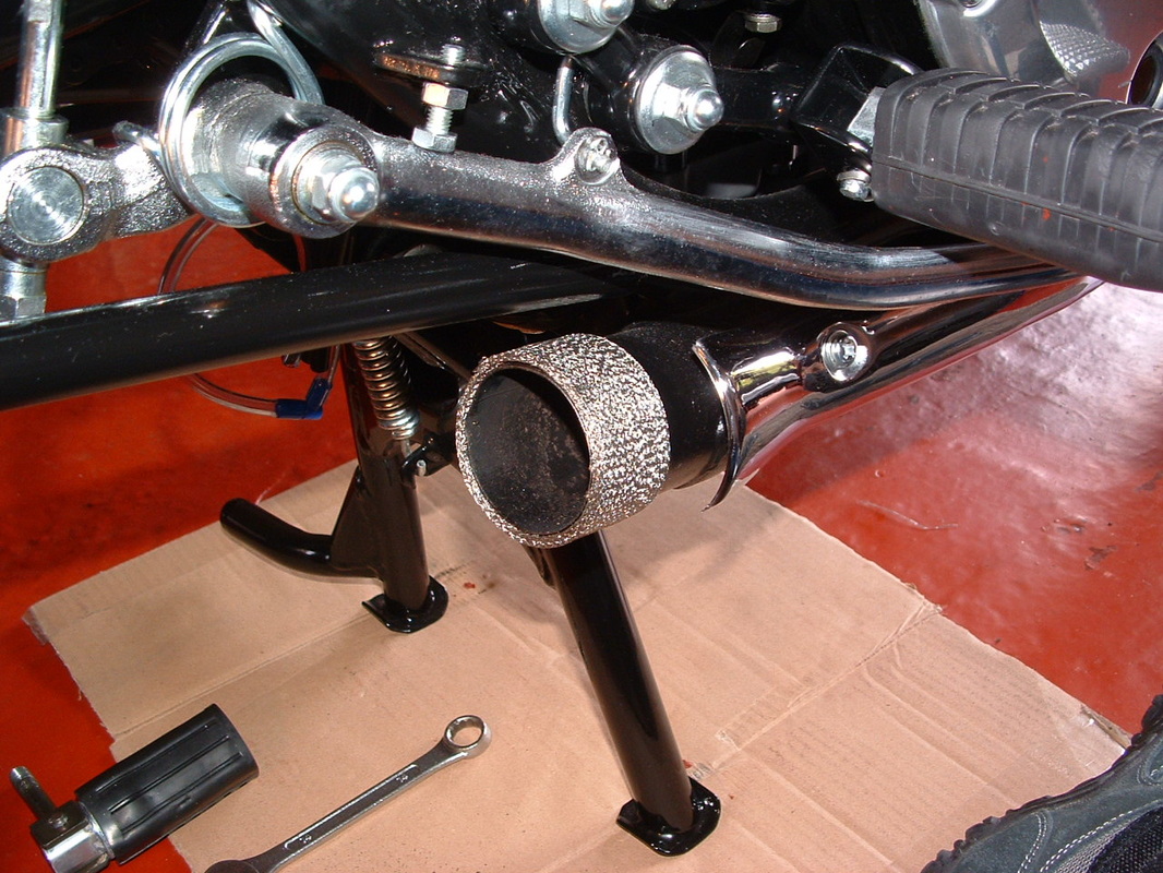
 New Muffler Fitted
Here is the muffler fitted. Note how tight the gap is to base of rear foot rest.
You can see the painted end now. Use heat resistant paint to copy the factory finish.
You can see the painted end now. Use heat resistant paint to copy the factory finish.

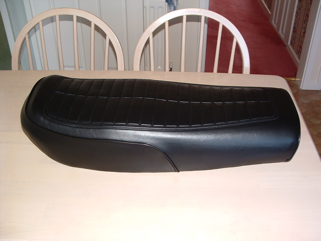
Old & New Seat Covers
The seat unit was next on the list to refresh.
The old cover is shown at top here.
Our new one is for this model and came from Japan.
It will be fitted to the new foam and re-painted seat pan.
The old cover is shown at top here.
Our new one is for this model and came from Japan.
It will be fitted to the new foam and re-painted seat pan.

Seat Components
Here are the other seat components which have been prepared for the rebuild.
We have new warning decals to stick in place when it is complete.
The kick starter is stowed under the seat for emergencies.
We have new warning decals to stick in place when it is complete.
The kick starter is stowed under the seat for emergencies.
Re-built Seat Assembly
This shows the new cover and foam - all fitted onto the re-finished seat pan
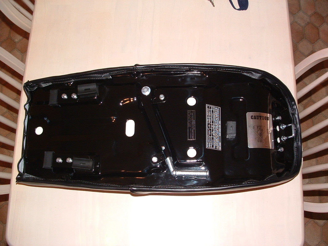
Restored Seat Base
The underside now has new rubbers for the front locating brackets.
The warning decals are now replaced. The under seat manual shows where these should go
The warning decals are now replaced. The under seat manual shows where these should go
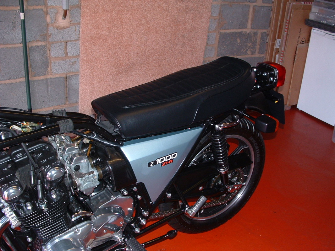
Testing Seat Catch Position
Here is the seat - back on the bike and getting the seat latch adjusted.
The length and angle of the catch bracket controls how far forward the seat can move against the tank.
It also ensures that the three support rubbers contact the frame correctly.
The length and angle of the catch bracket controls how far forward the seat can move against the tank.
It also ensures that the three support rubbers contact the frame correctly.
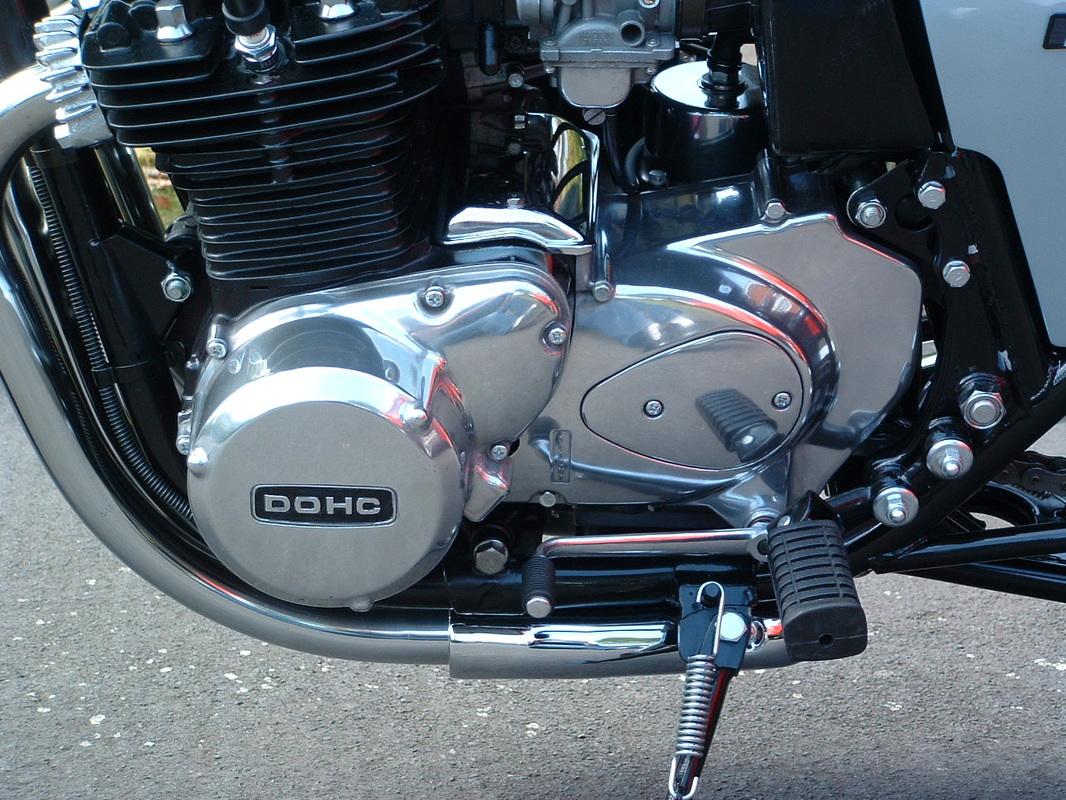
 Engine Case & Emblem Painting
The side panel badges are getting touched up - where the black or white paint has chipped over the years. The engine covers have a DOHC logo on each side which needs highlighting with black heat resistant paint.
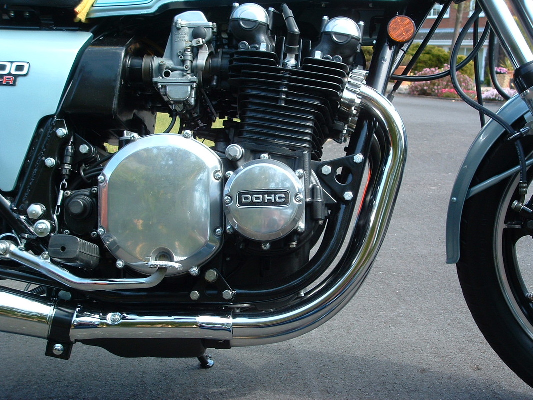
 Left Engine Detail
The left side of the engine, carbs & pipes is complete now.
You can see the DOHC logo has been given a black background again to make it stand out.
You can see the DOHC logo has been given a black background again to make it stand out.
 Right Engine Detail
The right side of the engine is also finished.
You can see the black highlighting on the outer points cover.
TIP - use a wooden kebab skewer or large cocktail stick to apply the paint without getting it onto the letters.
You can see the black highlighting on the outer points cover.
TIP - use a wooden kebab skewer or large cocktail stick to apply the paint without getting it onto the letters.
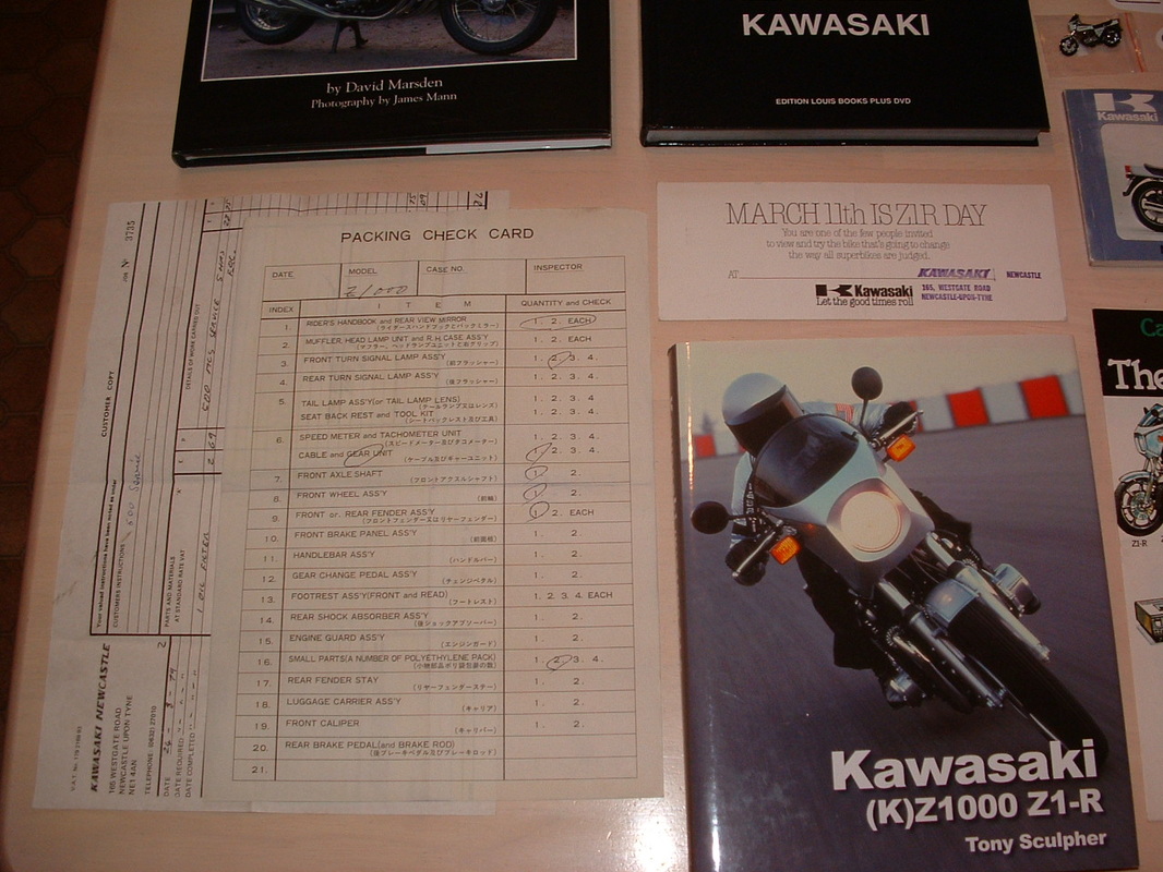 Rare Z1-R Documents
Here is the packing crate check list, a 1978 Z1-R service invoice and MOST RARE - a Z1-R UK Launch Day invite from Kawasaki.
These are all included in the bike history file, along with Tony Sculpher's excellent Z1-R Restorers Guide.
These are all included in the bike history file, along with Tony Sculpher's excellent Z1-R Restorers Guide.
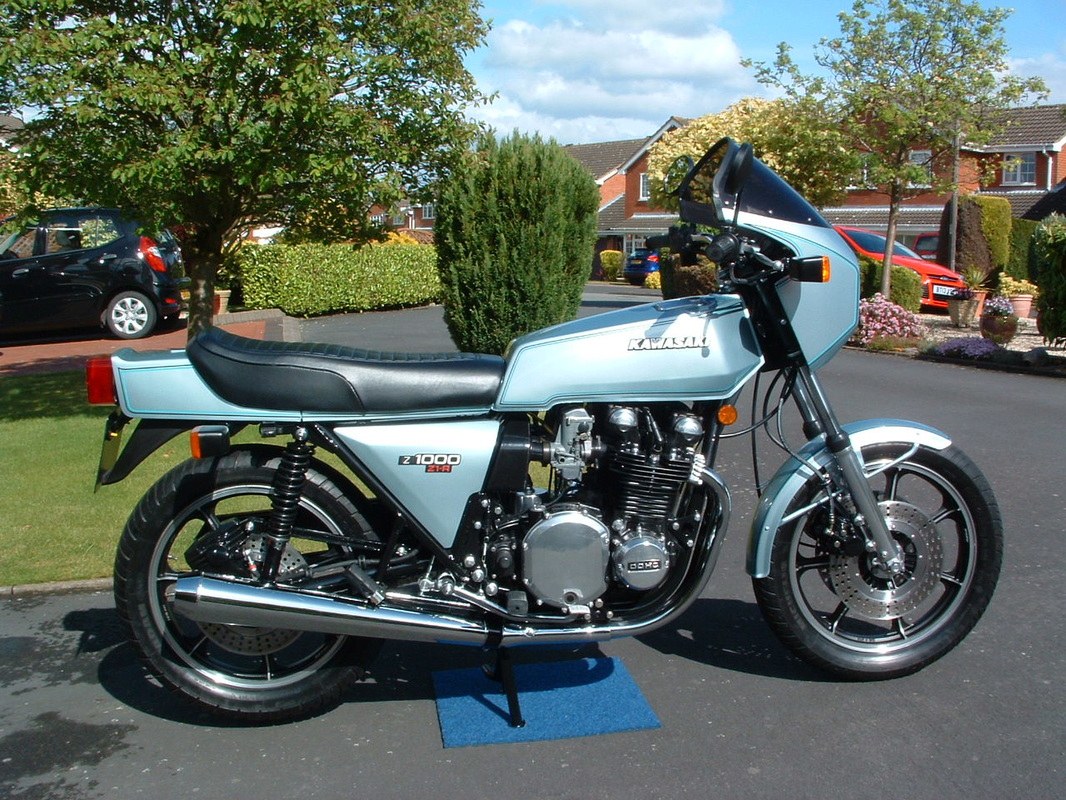 All Finished For 2015
Here is the completed rebuild.
The drilled brake rotors have been given a good clean up with scotchbrite.
The seat strap has not been fitted - because we like the clean low lines.
A new seat strap and fittings is included with the bike though.
The drilled brake rotors have been given a good clean up with scotchbrite.
The seat strap has not been fitted - because we like the clean low lines.
A new seat strap and fittings is included with the bike though.
 Ready For Another 38 Years !
The larger touring gas tank will stay with the bike as a spare.
The engine fins have been left black at the sides - although the original factory finish was to reveal the silver alloy at the outer edges.
This look is inspired by the modern SANCTUARY Zed specials coming out of Japan now.
The engine fins have been left black at the sides - although the original factory finish was to reveal the silver alloy at the outer edges.
This look is inspired by the modern SANCTUARY Zed specials coming out of Japan now.
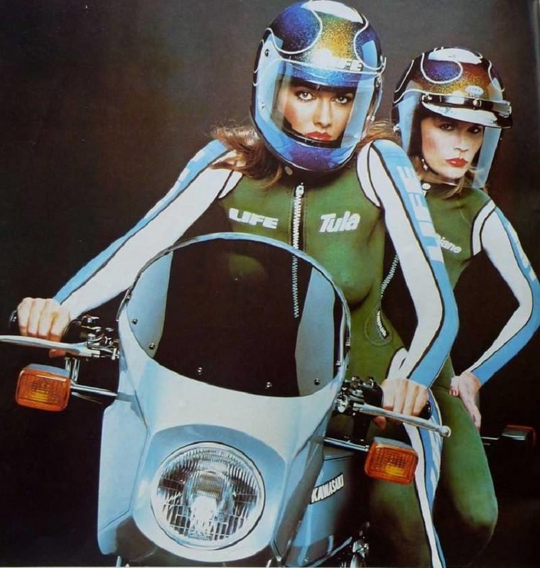 The Test Riders ! !
The Z1-R featured in a number of 1970's adverts.
This one is for LIFE helmets.
You can also get several scale models of the bike to build.
Perhaps you would like to build one yourself ? ?
This one is for LIFE helmets.
You can also get several scale models of the bike to build.
Perhaps you would like to build one yourself ? ?
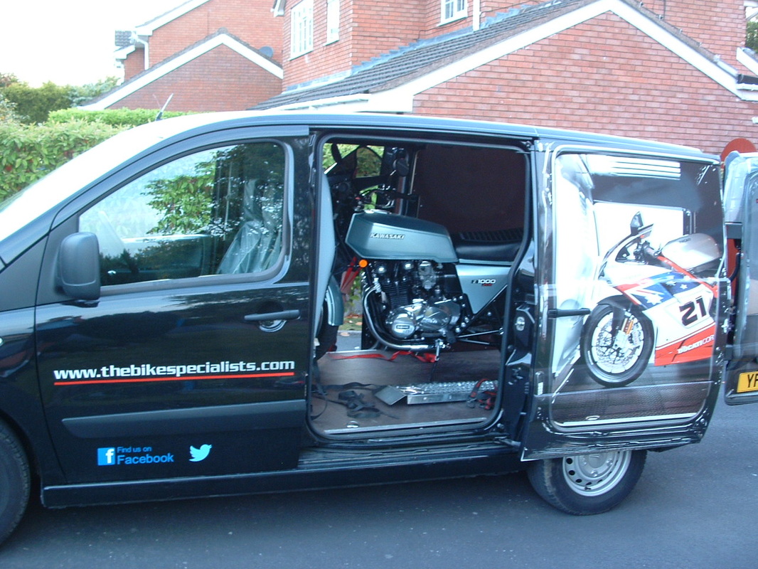 Off To A New Home
After a quick trip to get an MOT and an eBay advert our Z1-R was bought by a collector and soon heading up country.
Here she is - all loaded for departure.
Here she is - all loaded for departure.
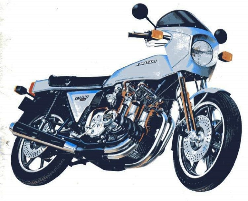 Z1-R Cutaway Illustration
Stay tuned for our next rebuild story.
Coming Soon
